This thread has been locked.

If you have a related question, please click the "Ask a related question" button in the top right corner. The newly created question will be automatically linked to this question.

DP83822IF: 4-level strap voltage not as expected

Part Number: DP83822IF
Other Parts Discussed in Thread: DP83822EVM

Tool/software:

Hi,

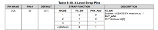
we are using DP83822IF in a SFP config. we are having a problem establishing a link through SFP, when we read back the registers we get the wrong values although they are set by a hardware straps.

also we ran a self test/ loopback test and came back w/o errors.

we started to follow the DP83822 Troubleshooting Guide.

In normal operation:

we found the the Vrbias = 0.987V Not the recommended 2.7V

Pin COL = 0.0280V instead of ~ 0.8V

Pin RX_DV = 0.0280V instead of ~ 0.8V

the Values are right in just two case when the IC itself is removed from the PCB or the reset line is LOW.

what we already tried:

1. replacing DP83822IF.

2. checking AVD & VDDIO voltages and replacing the ferrite beads w/ 0R.

3. checking all the resistor values on the PCB.

3. Pullup resistor 2.21K on the MDIO W.R.T VDDIO.

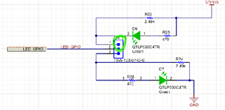
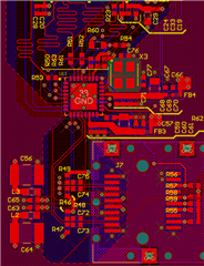
Could you please take a look at the Schematics and see if their is something missing or wrong? 

you can find the attached Schematics with the Hardware strap config at the top.

FX_PHY.pdf

  • Hi,

    The 2.7V on the RBIAS is a typo in the app note, it should be around 1V.

    When you read the strap values from registers 0x467 (SOR_1) and 0x468 (SOR2), what value are you reading? 

    Have you also checked the DP83822 power up sequency and verify it it is meeting the power up timing requirement?

    Thanks

    David

  • Hi David,

    the power up timings is within limits, and the 0x467 (SOR_1) and 0x468 (SOR2) equals 0x2001 , 0x0000 respectively. The registers are the same for our design and the Ti EVM board.

    we got the evaluation DP83822EVM and tested it with stm32F4 discovery to verify our setup. we got a link , but it doesn't ping although we will talcke this problem when we establish a link on our custom design.

    The voltage of the hardware strap after power up for our design and EVM are the same:

    Pin COL = 0.0280V

    Pin RX_DV = 0.0280V

    so, I think the hardware strap is not the main problem for establishing a link.

    Regarding our design something is preventing a link although we used the same Hardware strap config and same SFPs.

    thanks for your help in advance.

  • Hi Mohamed,

    Thank you for the update, David is on travel until tomorrow so I will help to support this.

    The registers are the same for our design and the Ti EVM board.

    Using a DP83822EVM in default configuration I see 0x467 = 0FC3 and 0x468 = 0000. How are you configuring the EVM to get 0x467 = 0x2001?

    Another question: Do you see the FX_LOS signal going high when the fiber connection is present? This would be Signal detect on the DP83822:

    In order for 822 to link up it needs to see this go high. This assumes you haven't changed the polarity of Signal detect in the fiber GENCFG register.

    Best,

    Shane

  • Hi Shane,

    1. Regarding the register 0x467 = 0x2001 we don't know how it got to this value , we were expecting 0x0FC3 , also we having a problem setting register SD

    polarity value to 1 when we set it and read it back the value doesn't change from 0 because our design is active LOW by default.

    2. Regarding the physical connection of FX_LOS (SD) in the EVM is is pulled up by default with R22 and is not connected to the SFP by default

    In our own design, I did the same as the EVM and pulled up the SD w/ external resistor 2.49K and still no link.

  • Hi Mohamed,

    Can you please share a picture of your DP83822 EVM setup?

    Since register 0x467 is an extended register, are you using the extended register access to read and write it? To read a register in the extended register set:

    1. Write the value 0x001F (address function field = 00, DEVAD = 31) to register REGCR.

    2. Write the desired register address to register ADDAR.

    3. Write the value 0x401F (data, no post increment function field = 01, DEVAD = 31) to register REGCR.

    4. Read the content of the desired extended register set in register ADDAR.

    Thanks

    David

  • Hi David,

    we got the EVM to ping and now the register read back is correct for both our design and EVM.

    I made sure everything(straps etc) is close as possible to EVM but still there are no link on our design.

    May be something is wrong with our routing?

    Thanks,

    Mohamed

  • may be intra pair or inter pair  length matching problem?

  • Hi Mohamed,

    Are you able to link up your design with the DP83822 EVM?

    With the register read now working, can you please dump out register 0x00 to 0x1F, registers 0x467 (SOR_1) and 0x468 (SOR2)? 

    On the MDI trace routing,

    1. All traces should have a trace length of less than 2 inches.
    2. For both intra-pair and inter-pair, length match within 50 mils for 1000M applications, or 100 mils for 10/100M applications
    3. Ensure a controlled impedance of 100 ohms differential.
    4. Recommend placing a keepout of size 5*w around the traces, where w is the width of the trace.

    Thanks

    David

  • Hi David,

    Registers:

                you can find all the register value in the pdf file attached.

    Routing:

              1. inter-pair length matching < 107 mils.

              2. intra-pair length matching < 22 mils.

              all other routing requirements are met.

    thanks for your help.

    .Reg_fiber.pdf

  • Hi Mohamed,

    100BASE-FX signal detect pin (LED_1) polarity is controlled by bit[0] in the Fiber General Configuration Register (FIBER GENCFG, address 0x0465). By default, signal detect is an active HIGH polarity. 

    If you change its polarity using register 0x465, are you able to link up with your design? 

    Thanks

    David

  • Hi David, 

    yes ,we tried it with our default HW config for SD in one of our PCB which was pull-down. In one of our previous attempts we changed the SD to pull-up (HW) 

    and disconnected the SD from SFP side to make the HW config exactly like EVM and still no link in either one.

  • Hi Mohamed,

    Are you able to take our EVM and see if it is able to link up with the link partner?

    Thanks

    David

  • Hi David,

    I found the source of the problem, the TX_disable pin of our specific SFP is pull-up by default disabling transmit signal when we connect it to GND , the link works instantly.

    Thank you helping us in troubleshooting. We appreciate it.

  • Hi David,

    We are still encountering an issue with the ping functionality.

    Our testing firmware works as expected on the EV Kit it successfully establishes a link and responds to pings using the statically assigned IP address. However, when using the same firmware on our custom PCB, the link is established, but pinging does not work.

    I have reviewed the relevant registers, and here are the observed values for both the EV Kit and our PCB:

    Register  EV Kit value PCB Value
    BMSR 0x2100 0x3100
    CR2
    0x4100
    0x100
    RCSR
    0x65
    0x65
    SOR1
    0xFEF
    0xFEF
    SOR2
    0x0000
    0x0000

    Additionally, I forced the values of the BMSR and CR2 registers to match the required configurations, but this did not resolve the issue.

    Please let me know if you have any suggestions or if there are other registers or tests, we should look into.

  • Hi Mohamed,

    Can you please check the strap configuration on the COL pin (Pin 29)? COL pin has to be in MODE 2 or 3 to set FX_EN. For now, register SOR1 shows it is being strapped to MODE 4 which disables the FX_EN.

    Can you also dump out the below registers for the fiber operation?

    Thanks

    David

  • Hi David,

    We have configured the COL (Pin 29) strap resistors to Mode 3 as requested. Additionally, the SD pin (Pin 24) is being driven high (value 1). Below is a summary of the relevant register values for your reference:

    Register Address Register Value Bitfield Bitfield value Note
    0x0001
    0x784d
    2 1
    0x000A
    0x4100
    14 1 FX_EN is set as expected due to COL strap configuration.
    0x0016
    0x0100
    4 0
    0x0040
    0xc11d
    6:5 00
    0x0403
    0x9fcf
    11:8 1111
    0x0465
    0xff00
    0 0
    SD pin is forced high (1), consistent with expected config.
    0x0467
    0x0bef
    - -
    Confirmed: COL strap mode is set to Mode 3.
    0x0468
    0x0000
    - -

    Do you have any suggested steps or diagnostic paths to further investigate and resolve the issue?

  • Hi, Omar

    Are you seeing this ping issue between your design and the DP83822 EVM? If you are, can you enable the EVM to generate the PRBS pattern, and put your design into reverse loopback? Below are example sequences of register reads and writes to perform BIST when using two DP83822 PHY's:

    // Reverse Loopback on PHY

    begin

    001F 8000 //Hard Reset

    0000 2100 //Disables Auto-Neg, Selects 100 Mbps

    0016 5000 //Enables PRBS packet generation

    0017 // check PRBS lock status

    end

    // Reverse Loopback on Link Partner

    begin

    001F 8000 //Hard Reset

    0000 2100 //Disables Auto-Neg, Selects 100 Mbps

    0016 0110 //Select Reverse Loopback

    end

    If you don't see any PRBS error with this reverse loopback, then the PHY and the MDI interface is ok. We then need to check the RMII timing between the PHY and the MAC to make sure there is no timing violation during the ping.

    Thanks

    David

  • Hi David,

    We tested the two PHYs in a peer-to-peer setup as you described (The EVM is generating PRBS packets, and our design is in reverse loopback mode), and the results showed zero errors (on the EVM errors counter).

    Could you please advise us on the next steps to debug the ping issue?
    Thanks
    Omar

  • Omar

    Can you share a block diagram of your overall ping testing setup? Are you trying to ping between the DP83822 EVM and your design? If it is, can you switch to a PC for the ping packet testing?

    If the EVM is generating PRBS packet and you are receiving the packet correctly, this tell me the MDI and the PHY itself is ok, and we will have to look at the MAC timing and MAC itself. 

    Are you able to send the ping with your design and does it work?

    Thanks

    David

  • Hi David,

    Missioned below the ping test setup and the loopback test scenario. Keep in mind that the same ping test setup is the same one performed on the EVM and passed.

    Reverse loopback test scenario:

    • On the board side:

    The board is set to reverse loopback mode:

    Register Value
    0x00F1 0x8000
    0x0000 0x2100
    0x0016 0x0006
    • On the EVM side:

    The board is set to generate PRBS packets:

    Register Value
    0x00F1 0x8000
    0x0000 0x2100
    0x0016 0x5000

    Continuously poll on the PRBS checker lock bit till it resets:

    R0x0016 >> bit[11]

    Read BICSR1 register for the error count.

  • Hi Omar

    The reverse loopback configuration on the link pattern does not look correct. Bit [4:0] of register 0x16 should be set to 0x10000 to enable reverse loopback. Please see below script for enabling reverse loopback

    // Reverse Loopback on Link Partner

    begin

    001F 8000 //Hard Reset

    0000 2100 //Disables Auto-Neg, Selects 100 Mbps

    0016 0110 //Select Reverse Loopback

    end

    You can also read the error count. To read the BIST error count, bit[15] in the BICSR1 must be set to '1'. This will lock the current value of the BIST errors for reading. Please note that setting bit[15] also clears the BIST Error Counter.

    Can you re-run the reverse loopback test with the correct configuration?

    Thanks

    David

  • Hi David,

    We’ve re-run the reverse loopback test using the correct configurations as per your last comment, and we’re still seeing a zero error count.

    Could you please advise on the next steps to help identify the root cause of the ping issue?

    Thanks in advance for your assistance.

    Omar

  • Hi Omar

    The DP83822 EVM does not have a MAC on it. When you are doing a ping packet test, are you jump wire to an external MAC? Is this the same MAC that you are using on your board? 

    Is it possible that you can take the router out of the ping setup and have the PC connected directly to the TX-to-FX media converter? 

    When ping failed, what error message do you see on the PC?

    Thanks

    David

  • Hi David,

    Just to clarify, the exact same MAC and firmware are used on both the EVM and our custom board. The only difference is in the physical setup while the EVM uses jumper wires to connect the MAC, our board has both the MAC and PHY integrated on the same PCB.

    We've also tried removing the router from the ping test setup, and there's no noticeable difference. In both cases, we consistently get the same error: "Request timeout."

    Thanks,
    Omar

  • Hi Omar,

    I went back and looked at your schematic again. Looking at it, I believe you have the RX_D0 and RX_D1 swapped, can you please confirm?

    Thanks

    David

  • Hi David,
    We swapped the two pins and reran the ping test it worked successfully.
    Thank you for your support!

    Best regards,
    Omar