This thread has been locked.

If you have a related question, please click the "Ask a related question" button in the top right corner. The newly created question will be automatically linked to this question.

TCAN1044-Q1: TCAN 1044 mode change time confirm

Part Number: TCAN1044-Q1

Tool/software:

Hi team,

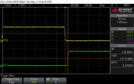
Mode change time in datasheet is required MAX:20us but the result we tested of normal to standby mode delay time is 22.43us.

We want to confirm it is guaranteed to occur of not to occur above the max value?

  • Hi Alan,

    We guarantee 20 us max. Hence, I would recommend to double check measurement (probe loading, timing reference, signal thresholds) and the datasheet conditions are met (Vcc, temp, the shown test circuit conditions), a different unit etc, as a deviation outside the limit is not acceptable, thanks. 

    Best Regards,

    Michael. 

  • Hi Michael,

    Thanks for your feedback. 


    could you double check ?  The SCH is as below, there is no capacitor on the signals, and the signal is from TCAN1044.   


    And about the test probe, I think it's ok to measure this low speed signal.

    And I double check TJA1044, the value is much higher than TCAN1044. 

  • Hi Alan,

    Probe seems to indicate 15 pF with schematic not fully showing other loads that could be connected to the CAN lines.
    I would recommend to use lower C probes while also avoiding dual probing CANH / CANL simultaneously due to the added load. Hence, use differential or active probes with minimal loading, thanks.

    Best Regards,

    Michael.

  • Hi Michael,

    Thanks for your suggestion!Harman will re-check.

    Do you have the waveform and setup info? Could you share your test waveform and setup with Harman? 

  • HI Alan,

    I do not have the waveform. As extensive validation was performed, I checked the validation data showing below the specified max and consistent with the data sheet.

    It is common for such timing differences with increased load and the setup is shown in figure 7-5 for typical RL as 60 ohms and CL < 100 pF. Increased overall load implies increased switching characteristics, thanks.

    Best Regards,

    Michael.