Other Parts Discussed in Thread: USB2ANY, ALP
Tool/software:
Hi,
We are conducting FPDLink3 communication between a display equipped with the DS90UB948 and a controller equipped with the DS90UB927.
I would like to implement MAP in this communication system, but I am having difficulties. Could you please provide some advice on possible solutions?
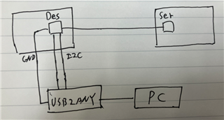
- I can connect USB2ANY to the deserializer's I2C and perform BIST.
- I also have the EVK kit, and I can connect it to a PC and run ALP to perform MAP.
Since the device with the DS90UB948 does not have a USB port, I am investigating ways to access the I2C to execute MAP.
Best,