


Tool/software:
There is a differential connection between R86 and LD_CTHODE, and the PCB layout is shown in the figure, where R85 is actually short circuited.
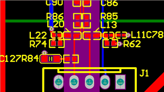
The current phenomenon is that R86 welds a 49.9R resistor with good signal quality and no obvious overshoot, but the pulse amplitude is low and the pulse driving current cannot trigger the LD; R86 short circuit processing may cause deformation of the pulse signal, but the pulse driving current can trigger the LD normally.
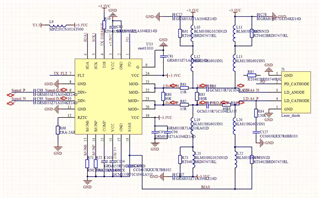
The PCB wiring impedance of the chip output differential signal is 100 ohms;
I would like to provide suggestions on the PCB terminal resistance impedance matching for the output current differential signal of this chip
I would like to provide suggestions on the PCB terminal resistance impedance matching for the output current differential signal of this chip
Looking forward to your prompt reply.
Thanks,
Adah
