This thread has been locked.

If you have a related question, please click the "Ask a related question" button in the top right corner. The newly created question will be automatically linked to this question.

TS3USBCA4: How to configure TS3USBCA410 on the GUI

Part Number: TS3USBCA4
Other Parts Discussed in Thread: TPS65994BH

Tool/software:

Hi Team, 

          Customer use ARL-HX+Barlow Ridge B1+TPS65994BH+TS3USBCA410. 


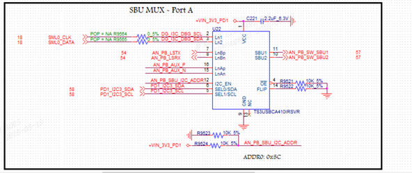
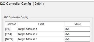
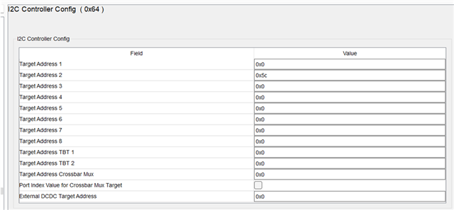
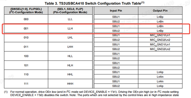
          TS3USBCA410 use i2c mode,address is 0x5C.TBT mode use LnBp/LnBn,DP mode use LnAp/LnAn. 

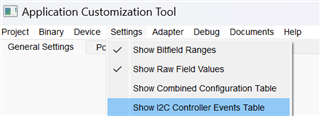
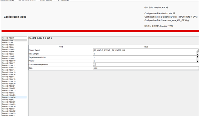
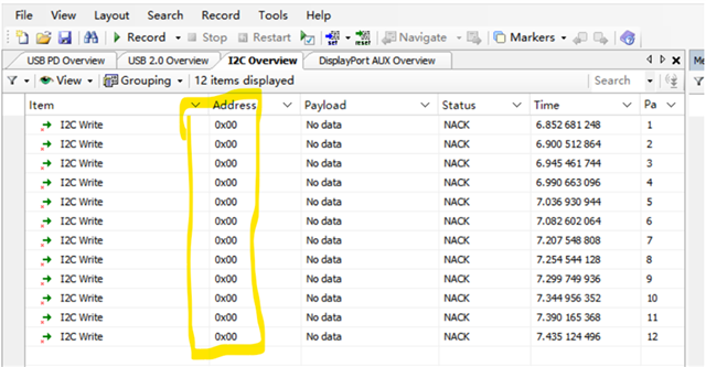
          I ues GUI(6.4.32)and firmware version(f909.12.15) configure PD fw.USB3.0 is OK,but TBT and DP can not work.

          How to configure TS3USBCA410 on the GUI, thanks.

  • Hi kaliun,

    The goal would be to get the following inputs on your SEL pins to correspond to the functionality you're looking for.
    Maybe start by probing the control pins and seeing if you're getting the expected logic first. 

    I'm also looping in the team that would be responsible for the TPS6599 GUI as it isn't something that my product line created or has familiarity with.

    Thanks,
    Rami

  • Looks like you are using I2C3 to control the TS3USBCA310. 

    You can have the PD control this in different scenarios by using the I2C Events Table. Instructions below:

    Go to Settings -> Show I2C Controller Events Table:

    You will see a new tab up top. Click it to open the I2C Events:

    Starting at Record Index 1 set the following information:

    Trigger Event (Could be I2C_CNTLR_EVENT__DP_ENTER_UU) the _UU or _UD on each if for orientation Upside-Up (UU) or Upside-Down (UD). This will cause the PD to send this I2C3 data over upon entry to DisplayPort. 

    DataLength = length of your I2C Data 

    Target Address Index = Is how you map this Record to the I2C Controller Config register 0x64. 

    0x64 Register's Target Address 1 == I2C Events Table Record Target Address Index value of 0

    0x64 Register's Target Address 2 == I2C Events Table Record Target Address Index value of 1

    etc... You will set one of these to the TS3USBCA310 I2C address

    Priority = leave at 0

    Orientation Independent = If you want the _UU or _UD to happen regardless of orientation, check this box

    Data = you payload you want to send to the TS3USBCA310

    Thanks,

    Chris

  • Hi Chris,

    Appreciate your support! 

    I try to use I2C3 to control the TS3USBCA410.

                I set 0X64 target address2 :0x5c,

                I2C controller events record index set:  Trigger Event (Could be I2C_CNTLR_EVENT__DP_ENTER_UD)

                                                                                DataLength =3

                                                                                Target Address Index=1

                                                                                Priority = 0

                                                                                Data=001


             When the Type-C to VGA cable is plugged in, the I2C address captured is 0x00,.Please help check if there is any problem with the above settings. Thanks.


  • Maybe this is simple solution. There is a 2 port design correct? Did you set 0x5C in Port 2's 0x64 register? 

    If you did then I may be misinformed about this section:

    0x64 Register's Target Address 1 == I2C Events Table Record Target Address Index value of 0

    0x64 Register's Target Address 2 == I2C Events Table Record Target Address Index value of 1

    It may be actually aligned for this device so try that was well. 

    Finally,

    The data length being set to 3 means you will send 3 bytes so will send 24 bits total LSByte: 0x01 0x00 0x00 : MSByte