This thread has been locked.

If you have a related question, please click the "Ask a related question" button in the top right corner. The newly created question will be automatically linked to this question.

TLK2501EVM: TLK2501 missing RXD parallel bytes

Part Number: TLK2501EVM

Tool/software:

Hi, 

we have connected the EVM to receive only and we are sampling the data on the RXD/CLK/ER/DV signals (2Gserdes, 100Mhz parallel - GTX_CLK). 

the device is syncing (RX_DV/ER deassert) and we are sampling the parallel data using an FPGA board (MPSOC based). 

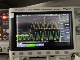
we observe sampling mismatches of whole 16bit words in specific places, after 'hffff data is transmitted for example. 

all the reset of the data seems correct. no loose of sync detected and no deassertion of ER detected. 

please assist in finding what might be the cause ?

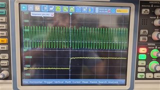
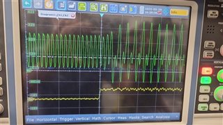
we suspect weak RX_CLK once higher current is pulled by the board. we observe it is changing "shape" once we receive those culprits words.  

Thanks

Doron

  • Hi Doron,

    Is my understanding correct that by "sampling mismatch", you observe the FPGA receives incorrect data after symbols like 0xFFFF are transmitted?

    Have you used a logic analyzer or scope to probe RXD lines relative to RX_CLK?

    When 0xFFFF is transmitted, do you correctly sample this on the FPGA and only observe issues on subsequent symbols?

    Thanks,

    Drew

  • Hi Drew, 

    your understanding is partially correct. we observed missing words (16bits) on the FPGA. we measured the RX_CLK connected to the FPGA (and only when connected) and saw it is distorted and of course this effects the data being sampled. we are now sampling the RX_CLK on a different FPGA bank and we do see those missing bytes now. we still have data integrity issues here and there but all bytes are received. another thing to consider is that the FPGA sampling bank is 3.3v. our calculations show that it should support  sampling the 2.5v signals coming from the TLK (VIL 2V). 

    for you second Q, we do not sample it with logic analyzer as we don't have one currently. 

  • Hi Doron,

    Thanks for clarifying.  This seems like a strange issue; is it possible to share to scope capture of the clock (and maybe one of the data lines) when this issue is occurring?

    Also, have you probed the supply voltage when this issue is observed?

    Thanks,

    Drew

  • Hi Drew, 

    i added 3 pics: 

    pic1 - idle state, valid asserts, clock

    pic2 - clock and dv when transmitting a sequence  of 0000 - ffff - 0000 - fffff  etc. 

    pic3 - same as pic2 , 1 of the data bits in yellow, clock in green, rx_dv in pink.

    pic1

    pic2

    pic3

    Thanks

  • Hi Doron,

    Thanks for sharing.  Looking at the captures, it's a bit surprising to me to see clock going below 0V.  Is there any scope setting I'm missing that could contribute to this?  It appears clock is DC coupled.

    Also, would it be possible to share the schematic?  You can share over E2E private message.

    Thanks,
    Drew

  • Hi, 

    sharing ALINX AXU3EG board schecmatics. this is not our board. its based on xilinx mpsoc. we are connecting RX wires from TLK to the 2 40-pin connectors J15/J16 which goes straight into the MPSOC chip. the FPGA board consist of a core module (ACU3EG) which sits on top of the dev board which exposes all interfaces. by the way, we also tried with another FPGA dev board, ZCU111 by Xilinx. we get the same phenomenon on the Rx wires. 

    ACU3EG_schematics.pdfAXU3EGB_schematics.pdf

  • Hi Doron,

    Drew is out of office and will respond back on Monday.

    Thanks,

    David