Tool/software:
Dear Texas,
At my company, we have a project to demultiplex an LVDS signal into 4 outputs. For that, we are using 2 TMUXHS4412 ICs in series to achieve a 1:4 demultiplexer configuration.
The first IC receives the LVDS signal, and through the SEL pin, we can select between 2 outputs. These 2 outputs are then routed to separate inputs of the second IC. Again, using the SEL pin, we can choose which output we want. In other words, by independently controlling the SEL pins of the two ICs, we can select which of the 4 outputs the signal should go to. The LVDS signal is below 10 GHz.
The first prototype worked well without any issues. Now, we had to use the second input of the first IC to inject another differential signal. This second signal is used alongside the original differential signal. That is, while before we only had one differential signal, now we have two. We are using 2 differential pairs: one is for data, and the other has termination at the end. Therefore, we are using 2 inputs to achieve 8 outputs after the second IC: two 1:4 configurations.
For the data signal, we use AC coupling capacitors 0.22uF at both the input and the output. For the terminated differential signal, we use 0-ohm resistors at both the input and the output too. On the final PCB, this second differential signal will have two 47-ohm resistors terminated to ground, while the first data differential signal will connect to an IC.
The second prototype worked fine initially, but over time, the outputs for the terminated signal stopped working. The data signal outputs are working perfectly. We measured the outputs of the terminated signal, and the ones that stopped working show no continuity with multimeter. We replaced the 0-ohm resistors with 0.22 uF capacitors at the input and output and new TMUXHS2212 ICs, and so far it seems to be working. What could be the reason for the outputs getting damaged when using resistors? It happened on 3 PCBs. Is it always recommended to use capacitors?
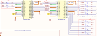
I’m attaching the schematic.
https://ibb.co/pBDNpFqN
R1, R4, C9, C10, C11, C12, C13, C14, C15 and C16 are 0.22uF capacitors for data differential signal.
R27, R28, C21, C22, C23, C24, C25, C26, C27 and C28 were initially resistors 0r which were all replaced by 0.22uF capacitors.