This thread has been locked.

If you have a related question, please click the "Ask a related question" button in the top right corner. The newly created question will be automatically linked to this question.

TCAN1044-Q1: Please review the schematic

Part Number: TCAN1044-Q1
Other Parts Discussed in Thread: ESD2CAN24-Q1

Tool/software:

Dear TI experts,

My customer made their schematic using TCAN1044-Q1. Could you review this schematic and check some questions?

1. Please check that if there are any points to fix for better performance.

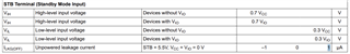
2. Could you check the value of minimum pull-up current for operating STB pin? Because we need to check that it is under the value that MCU can send.

And where can I find the basis in the datasheet?

3. Should I add pull-up or pull-down for TXD and RXD pin?

Please check this issue. Thanks.

Best regards,

Chase

  • Hi Chase,

    1.  0 ohms place holders (to be readjusted if needed) can be placed on RXD / TXD, split termination should be 60 kohms each and 4.7 nF (unless the chosen components are intention per system needs), ESD can be placed closer to connectors after the bus caps. Please promote ESD2CAN24-Q1 for CAN applications.

    2.  Please see below:

    3. Not needed, Only if TXD output of the controller is open-drain, thanks. 

    Best Regards,

    Michael. 

  • Dear Michael,

    Thank you for your support.

    1. I cannot find the information about the value of termination resistors and capacitors. Maybe you are saying about R48,R49 and C57. Can I find it (60Kohms and 4.7nF) in the datasheet?

    2. About the pull up current, It only needs 1uA to operate STB pin. Is my understanding right?

    Best regards,

    Chase

  • Hi Chase,

    The CAN physical layer requires that two nodes in the system have 120-ohms of termination for a total of 60-ohms between CANH and CANL. Unterminated nodes may include partial termination to help dampen signal reflections so long as the total bus load is not impacted too heavily - this will depend on the number of nodes that include partial termination as each will add additional load to the bus. For a relatively small system (a dozen or so nodes), 22k-ohms of partial termination is fine as this would leave the equivalent load around 58-ohms (TCAN1145 specifies performance down to 50-ohms or 45-ohms for extended load conditions). 
    Split termination is typically in a range from 4.7nF - 100nF, with the most common value being 4.7nF. I don't see any issue with the 47nF here unless there is specific concern for a target noise frequency (this is very uncommon).

    The STB pin has an internal pull-up to Vio (or Vcc). In order to drive a low-level input the MCU will need to sink the current from this pull-up and be capable of driving a low-level voltage on the pin. The IIL specification for this pin describe a test case where 0V is applied to STB when the Vio pull-up reference is 5.5V. The resulting output current from the internal pull-up was 20uA maximum meaning that the signal driver (the MCU in an application case) needs to drive 20uA or less in order to drive a low-level voltage on this pin. As this is a very weak internal bias pretty much any MCU will be able to drive it without an issue. 

    Let me know if you have any more questions.  

    Regards, 
    Eric Schott