This thread has been locked.

If you have a related question, please click the "Ask a related question" button in the top right corner. The newly created question will be automatically linked to this question.

DP83TC814R-Q1: DP83TC814RRHARQ1

Part Number: DP83TC814R-Q1

Tool/software:

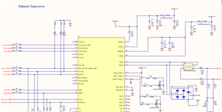
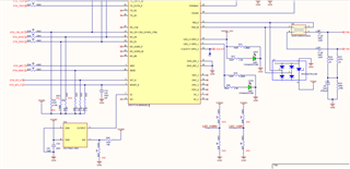
Could you please review the circuit for RMII slave mode configuration ad provide input

  • Hi Nayan,

    I am reviewing the schematic and will have feedback shortly.

    Best,

    Evan Su

  • I have an updated version, 

  • Hi Nayan,

    The schematic generally looks good. I have just a few notes:

    • For RMII slave mode, there is expected to be a 2.49k pullup resistor applied to RX_D1, it seems to be currently DNI in your schematic
    • The MDIO line requires a pull up resistor which is not shown here, maybe you already have it somewhere else in your design
    • I see the reset line has a 1 uF capacitor C33 on it. I think this would typically be a debouncing capacitor for a physical switch. If the reset line is electronically controlled, this capacitor is not necessary.
    • Are you using a shielded or unshielded cable? If shielded it may be helpful to add provisions of resistors and capacitors to isolate the board ground from the cable ground, in case there turn out to be EMI issues
      • But since it looks like the MDI terminations are referenced to a generic GND, I assume you are using an unshielded cable, in which case this is less important.

    Best,

    Evan Su

  • ok I will look into the comments shared, Could you please share the isolated connectors that can be connected to TRD_M & TRD_P lines?

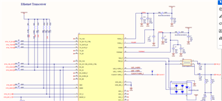
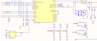
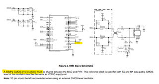
  •  Hi, Thanks for the input, I have one more query , In RMII slave mode the 50MHz oscillator used should it be external or is it coming from uC (because MCU STM32 is host in our application)?

    Thanks in advance

  • Hi Nayan,

    ok I will look into the comments shared, Could you please share the isolated connectors that can be connected to TRD_M & TRD_P lines?

    The isolation I mentioned isn't really related to TRD_M and TRD_P or a special type of connector. My meaning was that in a case where the cable is shielded, typically the ground used by the connector + shield and the ground used by the PCB are different nets, and then these nets can be connected or disconnected through the isolation capacitor and isolation resistor placeholders as needed. The MDI termination network would typically be referenced to the connector/shield ground instead of the PCB ground in this case. If you are not using a shielded cable then typically this does not matter, it's common for there to only be one ground in the design then.

    I have one more query , In RMII slave mode the 50MHz oscillator used should it be external or is it coming from uC (because MCU STM32 is host in our application)?

    I haven't personally tried that, but the 50 MHz oscillator input could come from any source that meets the clock specifications in section 7.6 of the datasheet.

    Best,

    Evan Su