This thread has been locked.

If you have a related question, please click the "Ask a related question" button in the top right corner. The newly created question will be automatically linked to this question.

DS90UB964-Q1: DS90UB964-Q1 EVM POC insertion loss question

Part Number: DS90UB964-Q1

Tool/software:

Hi,

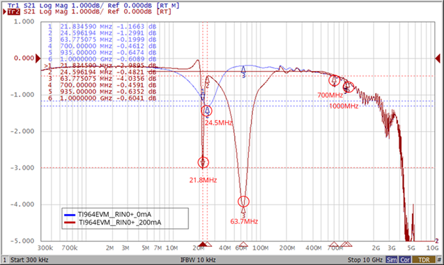
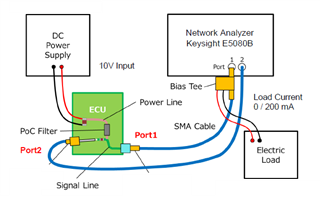
We actually measured the insertion loss of the DS90UB964-Q1 EVM, and tested it in loaded and unloaded states. We found that anti-resonance occurs in the frequency band below 100MHz. The blue curve is unloaded, and the brown curve is loaded. We want to know whether the cause of the load is related to the POC combination?

In addition, will the occurrence of anti-resonance also affect the actual image transmission quality?

  • Hi Lucy, 

    Would you be able to elaborate on the test set up here? Was a cable connected in this set up? 

    PoC solutions with no load and under load will have varying results as the load will change the self resonating frequency of the filter will increase. 

    When using FPD-Link devices a channel specification is provided with total channel requirements and PCB/cable recommendations. So long as total channel requirements are met we would not expect this to impact the image transmission quality or operation of the devices.

    Best,

    Zoe

  • Hi Zoe,

    Our test conditions are that there is no cable connected, only the PCB part is measured, from the IC side to the component side of the CN connector, and the load part is 200mA.
    As shown in the previous actual measurement figure, there is anti-resonance phenomenon in the frequency band below 100MHz, resulting in non-compliance with the insertion loss, as shown in the following table:

    The PCB insertion loss requirement of FPD III Link should be that the entire frequency band from 1M to 1GHz must meet the specification, right?
    If it does not meet the specification, such as anti-resonance phenomenon in the frequency band below 100MHz, will it affect the image transmission quality in actual use?

  • Hi Lucy,

    Do you have any photos of the test setup? Based on the info here it doesn't seem like the PoC network meets our channel specification. Do you know if the customer has a preferred vendor for PoC inductors who could help them with a network for their system?

    Best,

    Thomas

  • Hi Thomas,

    The test architecture is as follows:

    The customer did not specify the manufacturer.

    Please help answer the following questions:

    The PCB insertion loss requirement of FPD III Link should be that the entire frequency band from 1M to 1GHz must meet the specification, right?
    If it does not meet the specification, such as anti-resonance phenomenon in the frequency band below 100MHz, will it affect the image transmission quality in actual use?

  • Hi Lucy,

    There are a few components of this to consider:

    • You are correct that the FPD-Link insertion loss & return loss specifications should be met across the full frequency band
    • The requirement which must be met to ensure stable operation is the total channel requirement. The PCB and cable budget provide recommendations of how this may be split into two PCBs, along with a cable. If customers choose to allocate more insertion loss on the PCB, and less on the cable, that is okay with the understanding that the total budget must be met.
    • When evaluating PoC networks for our latest devices (FPD UB97x devices) we do work with vendors to look specifically at the insertion loss & return loss of the PCB with the PoC network under study. This is generally done at the highest temp rated for the module (often 105C) & the max current load of the inductor. We use this data to certify that our channel spec can be met using a specific PoC solution.

    Hope this provides some clarity here.

    Best,

    Thomas