This thread has been locked.

If you have a related question, please click the "Ask a related question" button in the top right corner. The newly created question will be automatically linked to this question.

DS250DF230: configuring recovered clock output RCK0

Part Number: DS250DF230

Tool/software:

Hello,

in our application we use two DS250DF230 to send data over an ambitious channel from 5Gbit/s to 6,25Gbit/s. For an extension it should be perfect to use the recovered clock output as syncronized reference for additional equipment on both sides.

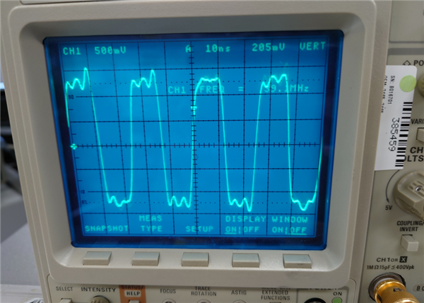
We followed the instructions in the programming manual and in fact, the output is putting out some signal. But instead of the expected rectangular clock-signal in the 30Mhz-Range, there some instable sinus in 10khz-range or even slower rising and falling edges. With unlocked CDR or switching off the output there is no signal, so we assume the basic configuration is right.

As we run actually with manual clock-rate-configuration, we tried setting the rclk-divider(rclk_sel_div_lv, mr_cipri_clk_div_sel_ov set to one) to different values. Output changes somehow, but we still have something like mentioned above.

For the desired purpose we aren't limited to the bitrates we used before, so we tried some standard-bitrate-configurations as well(set in 0x2F), unfortunately without success.

Does anybody have more experience with this output and can give us some hint(s) how to get this running?

Many thanks in advance,

Philipp

  • Hi Philipp,

    Thanks for your detailed description of the issues you're observing.

    Is it possible to share the exact programming sequence you've tried implementing?

    Thanks,
    Drew

  • Hi Drew,

    many thanks for your fast reply! Of course this is possible. On our current hardware-implementation(s) we configure the DS250DF230 with a microcontroller over SMBUS, so i can give the (slightly simplyfied) code, which represents the (startup-)sequence.:

    • The parameters of the write-/mod-functions are <register>,<value>,<mask>.
    • The reference-clock is 25Mhz.

    First, we perform a reset at every system startup:

    ti_select_registerset(SHARED);
    ti_mod_register(0x04,0b01000000,0b01000000);//Reset shared registers

    Then, we set some general channel-settings for both channels seperately, "reg_sel" represents the channel, e.g.:

    ti_select_registerset(reg_sel);
    ti_mod_register(0x00,0x04,0x04);//Reset Channel-Registers
    HAL_Delay(50);//Delay
    ti_select_registerset(reg_sel);
    ti_write_register(0x31,0b01000000);//adapt mode 2
    ti_write_register(0x3D,0b10001111);//FIR activate Pre-/Post-cursor, set output-level(+15))

    After that we perform some routines as default, for example Output-polarity-change by FIR-sign-change with read-modify-write. These functions are intendet to be executet later from the UI as well.

    Last, we run one "set-bitrate"-routine for both channels:

    ti_fir_set(&cmain,&cpre,&cpost);//sets FIR for both channels.

    ti_select_registerset(CH0);
    ti_write_register(0x60,br6062);//Datarate register
    ti_write_register(0x61,br6163);
    ti_write_register(0x62,br6062);
    ti_write_register(0x63,br6163);
    ti_write_register(0x64,0xFF);//PPM-tolerance to max
    ti_mod_register(0x09,0x04,0x04);//enable override for divider
    ti_mod_register(0x18,br18,0x70);//divider

    //here're the lines we tried to activate the output with:
    ti_mod_register(0xAC,0x08,0x08);//mr_cpri_clk_div_sel_ov
    ti_mod_register(0x3F,0x10,0x30);//divide ratio 320
    ti_mod_register(0x1A,0x04,0x04);//enable RCK0-Output

    ti_cdr_reset(CH0);

    ti_select_registerset(CH1);
    ti_write_register(0x60,br6062);//Datarate register
    ti_write_register(0x61,br6163);
    ti_write_register(0x62,br6062);
    ti_write_register(0x63,br6163);
    ti_write_register(0x64,0xFF);//PPM-tolerance to max
    ti_mod_register(0x09,0x04,0x04);//enable override for divider
    ti_mod_register(0x18,br18,0x70);//divider
    ti_cdr_reset(CH1);

    ...where the variables are set before with respect to the selected bitrate. For 6,25Gbit/s e.g.:

    br6062 = 0x80;
    br6163 = 0xBE;
    br18 = 0x20;
    cmain=0;
    cpre=0;
    cpost=0;

    Thank you!

    Philipp

  • Hi Philipp,

    Thanks for sharing your configuration.  I looked over it and don't see any issues.

    I'll see if this is reproducible on my end.  I can update you next week on my findings.

    Thanks,

    Drew

  • Hi Drew,

    that sounds great, i'm really looking forward to your findings!

    Thanks,

    Philipp

  • Hi Philipp,

    I tried reproducing your observations in lab.  I sent a 6.25 Gbps PRBS31 signal to RX0 of the DS250DF230 and was able to observe a ~39 MHz clock signal from TEST0/RCK0.

    I've also attached my register dump in case you find this useful.  I believe key registers were similar to yours (configured CDR and recovered clock registers).

    ds250df230_rclk_cfg.cfg

    Unfortunately, the register dump does not include register 0xAC, but I separately confirmed it to be 0x5D.

    A couple other thoughts:

    • With 0x1A[2] = 0, I observe a ~50kHz sinusoid, ~50mVpp.  Not sure if this is somehow related to what you were observing.
    • My current hypothesis is that something is somehow not quite right in your configuration.  I'd recommend doing some testing to confirm your register write/mod functions are working as expected.

    Thanks,

    Drew

  • Hi Drew,

    Many thanks for your deep investigation! It now works like a charm. Honestly i dont know exactly why, additionally to configuration i guess i must check the hardware as well.

    Thanks again and have a nice rest of the week,

    Philipp

  • Hi Philipp,

    Glad to hear that you were able to fix the issue!

    Out of curiosity, were you able to identify what the issue was on your side?

    Thanks,
    Drew