This thread has been locked.

If you have a related question, please click the "Ask a related question" button in the top right corner. The newly created question will be automatically linked to this question.

DS160PR810: Voltage Mismatch Correction in 9.2Gbps SLVS-EC Transmission

Part Number: DS160PR810
Other Parts Discussed in Thread: DS100BR410

Tool/software:

I want to perform transmission and reception on a 9.2Gbps SLVS-EC (almost PCIe 4.0).

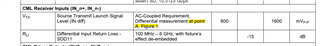
The differential output voltage of the Tx device is 160 mVpp, while the specification for the differential input voltage of the Rx device is "400 mV or higher."

Since the Rx device is a general-purpose differential signal receiver and does not comply with the SLVS standard,

there is a mismatch between the Tx and Rx differential swing voltages.

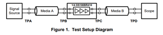
I want to resolve this mismatch by inserting a DS160PR810 between the Tx and Rx to achieve an 8dB gain—from 160 mV to 400 mV.

I would like to know if the gain is sufficient. According to the datasheet,

the flat gain is up to 2dB and the EQ (CTLE) is up to 18dB @8GHz,

so can it be interpreted that the differential voltage swing (eye height) can be boosted by 20dB?

If this interpretation is incorrect, please let me know the maximum gain that can be achieved with the DS160PR810.

Additionally, the datasheet does not specify the input differential voltage range; can this IC receive signals within the range of 160 mV to 280 mV?

inquire aout DS160PR810.pdf

  • Hello Tomoki-san,

    Using a linear redriver (DS160PR810), we are boosting the high frequency content and VOD is not affected. The only way to increase VOD using a linear redriver is by increasing Flat Gain (DC Gain). Flat gain is gain for the whole frequency spectrum of the signal. This increases the eye diagram height. Please see this link regarding linear vs. limiting redrivers: https://www.ti.com/content/dam/videos/external-videos/en-us/5/3816841626001/6144123457001.mp4/subassets/difference_between_linear_limited_redriver-final.pdf 

    We recommend using the IBIS-AMI model of this device plus your own transmission line S-parameter model to do signal integrity analysis. This IBIS-AMI model can be requested using the Request more information section on the DS160PR810 product page.

    You may also consider DS100BR410, which is a limiting redriver and provides options to adjust output VOD.

    Best,
    David

  • Thank you for your response and recommendations.
    I understand that what cannot be achieved without a limiting redriver.
    Regarding the proposed DS100BR410, it specifies a Source Transmit Launch Signal AC-Coupled Requirement with a Level (IN diff) of 600~1600mVpp.
    Can this IC accommodate the voltage range of 160mV~280mV that we are working with?
    If it cannot, could you please recommend another limiting redriver?

  • Hi Tomoki-san,

    The device was characterized with an input range of 600-1600mVpp.  Note that in this test case, high frequency parts of the signal could still be significantly attenuated by the pre-channel loss.  For example, for a 1000mV source transmit amplitude and a channel with 20 dB of loss at 5 GHz, components of the signal at 5 GHz would be attenuated to 100mV.

    I would expect this device to work with an input range of 160mV-280mV.

    In order to use this device with a low amplitude input, I would encourage disconnecting ENx pins from SDx pins.  Signal detect may not work as expected with such a low amplitude input signal.

    Please consider getting the evaluation board for this device so you can test this out.

    Thanks,

    Drew

  • Thank you for your response. Do you mean that the Vtx specification is based on Point A in Figure 1 of the DS100PR410 datasheet, and that it does not consider the attenuation or reflection along the transmission path—so that the differential voltage at Point B immediately before the IC input will be lower?

    If that is the case, I would like to ensure that the design can guarantee an input voltage to the IC in the range of 160 mV to 280 mV. One approach would be to use SI simulation with the IBIS AMI model available on the website, along with the actual PCB pattern, to verify whether the RX device’s eye requirements are met. If there is another method you can suggest, please let me know.

    Best regards.

  • Hi Tomoki-san,

    Do you mean that the Vtx specification is based on Point A in Figure 1 of the DS100PR410 datasheet, and that it does not consider the attenuation or reflection along the transmission path—so that the differential voltage at Point B immediately before the IC input will be lower?

    Yes, this is correct. The higher frequency components of the signal will be through the channel, so the amplitude of these at Point B will be lower.  Note that low frequency components of the signal will be less attenuated.  This causes ISI jitter, which CTLE is designed to compensate for.

    We can share the IBIS-AMI model with you.  Are you able to share your estimated insertion loss at 4.6 GHz for Media A and Media B?  Also, what is your RX eye requirement?

    Thanks,

    Drew

  • I apologize, but since the Eye mask on the Rx side cannot be disclosed, please focus on the Rx side of the redriver and Media A.
    The contents included in Media A are as follows:
    - Coaxial cable 140mm: insertion loss -3dB @4.6GHz
    - PCB pattern 50mm: insertion loss -1dB @4.6GHz
    Due to this insertion loss, we expect that a differential voltage signal source of 160mVpp to 280mV will be input as 100mVpp to 175mVpp.
    Will the redriver be able to handle this?

    Also, using the values from the datasheet for Source Transmit Launch Signal level and differential input loss:
    600mV/5.623(-15dB) = 106.7mV
    Isn't the argument that a differential voltage of more than 106.7mV is required at the redriver end incorrect?

  • Hi Tomoki-san,

    Thanks for the additional information.

    It's not clear to me where you're referencing the -15 dB specification from.  Are you using -15 dB from the differential input return loss specification?  If so, this is not the correct application of the return loss.

    I will look into creating a similar proof of concept in lab.

    Thanks,

    Drew