Part Number: DP83867IS
Tool/software:
Hi All,
I have a question about the DP83867IS 4-level strap.
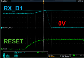
Could you please tell me when the hardware settings based on the voltage division of the strap pins are reflected in the PHY?
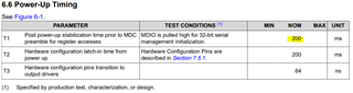
Could you please tell me the RESET threshold and how long it takes for the settings to be reflected?
Best Regards,
Ishiwata