This thread has been locked.

If you have a related question, please click the "Ask a related question" button in the top right corner. The newly created question will be automatically linked to this question.

TUSB2E11: More eUSB2 and USB signal configurations

Part Number: TUSB2E11

Tool/software:

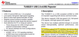
Application : The eUSB2 Repeater operates in FS mode (12MHz) and is placed on the device side...

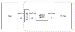
In this case, the length of the eUSB2 layout path will increase. Therefore, we have some questions for you.

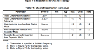
  • What is the standard for the length of the eUSB2 layout path with the eUSB2 repeater?
  • Is it necessary to configure the eUSB2 and USB2 signals?
    • If the answer is Yes,
      • Could you provide the repeater’s power on sequence and we want to know the interval between “ reset release ” & “ I2C start working ”
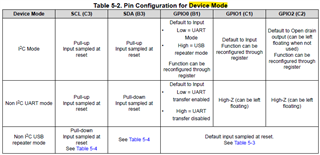
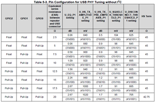
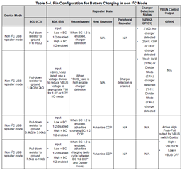
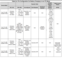
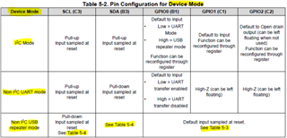
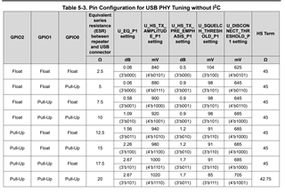
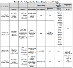
      • Could you provide more information for systems without an I2C interface ?

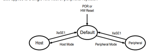
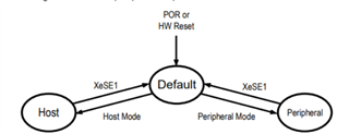
(e.g. Pin Configuration for Host Mode, System Implementation without I2C)

  • Hi,

    The eUSB2 spec can be found here for reference: https://www.usb.org/document-library/embedded-usb2-eusb2-physical-layer-supplement-usb-revision-20-specification-rev-12

    The spec has the host impedence as loss profiles defined as follows. The device side repeater should fit within these guidelines as well.

    The repeater will startup in the default state and will be configured into either peripheral or host mode. The host or device will program it as such.

    Startup information for GPIO mode can be seen in section 8.4.8.

    Its best to configure the device in I2C mode so you have equalization options available.

  • Hi,

    The table 7-6 in the eUSB2 spec is for High-Speed Channel Requirement. Could you tell me the circuit/layout limitation of TUSB2E11 in full speed mode (12MHz)?

    e.g.

    • What is the standard for the length of the eUSB2 layout path with TUSB2E11?
    • Is it necessary to configure the eUSB2 and USB2 signals?
      • Depends on PCB layout?
      • When is signal configurations not requested?
      • Is it okay to use the default settings for TUSB2E11 in full speed mode?

    I studied the the TUSB2E11 datasheet. Regarding GPIO pin configuration, it seems that it is not only related to signal configuration but also to battery charging, such as the following. What Pin Configuration is for Host Mode?

    This will affects the circuit design, so we would like to know what is necessary in this case. (e.g.I2C interface or GPIO pin configuration)

    • If the I2C interface is required, could you provide the repeater’s power on sequence? we would like to know the interval between “ reset release ” and “ I2C start working ”.
  • Hi,

    working on gathering this info now, I will get back to you soon.

  • Hi,

    The table 7-6 in the eUSB2 spec is for High-Speed Channel Requirement. Could you tell me the circuit/layout limitation of TUSB2E11 in full speed mode (12MHz)?

    Hi, we do not have a reference PCB trace length for this, but I recommend keeping the loss of the trace under 2.67dB of loss.

    What is the standard for the length of the eUSB2 layout path with TUSB2E11?

    We typically have our eUSB2 repeater designed for HS/FS/ and Ls operation, so we use the tightest constraints to determine the acceptable PCB length.

    A good rule of thumb for FR4 material is 0.2 dB/in/GHz this translates to 0.0002dB/in/MHz.  For a 12MHz signal the loss per inch will be 0.0024 dB/in. This means a trace for 416 inches will have a loss of ~1dB. You should be able to use a very long trace without issue. For this reason the signal condition in our repeaters only affects HS mode.

    When is signal configurations not requested?

    I'm not sure what you mean here.

    Is it okay to use the default settings for TUSB2E11 in full speed mode?

    By default settings, do you mean floating the GPIO0,1,2 pins?

    What Pin Configuration is for Host Mode?

    This configuration signal is sent by the Host, it cannot be pre-programmed. Configuration is done by the SoC over eUSB2 and it is not related to GPIO pins.


    What is the loss for your channel at 6MHz?

  • Hi,

    Q:When is signal configurations not requested? 
    >> I'm not sure what you mean here.
    I would like to know in which cases it is not necessary to set the signal configuration.

    Q:By default settings, do you mean floating the GPIO0,1,2 pins?
    No, I mean that Is it okay to use the default settings for TUSB2E11 register in full speed mode?

    Q:What Pin Configuration is for Host Mode?
    This configuration signal is sent by the Host, it cannot be pre-programmed. Configuration is done by the SoC over eUSB2 and it is not related to GPIO pins.
    In the non-I2C interface case,TUSB2E11 provide the GPIO to set up the eUSB2 and USB2 signal compensation as shown below.


    The description in the TUSB2E11 datasheet applies to the eUSB2 in device mode. Therefore, we would like to know what Pin Configuration is for Host mode? This setting will affect whether the GPIOs are pulled up or pulled down.


    Thank you for your assistance!

  • Hi,

    I think you may be confusing device mode and peripheral mode.

    In the datasheet, device mode refers to the 3 ways the TUSB2E11 can be set up (I2C mode, UART mode, or GPIO mode). This has nothing to do with host or peripheral operation.

    The tables referred in the datasheet are here showing how changing the GPIO0,1,2 signal will affect the device:

    In all 3 device mode the TUSB2E11 will initialize into the default state and will require either the host or peripheral to configure it into host or peripheral mode.

    hardware configuration done by the GPIO pins on this part is different from the Host or Peripheral configuration done by the eUSB2 bus. The Hardware configuration of the TUSB2E11 will set nothing more than the following aspects of the USB2 side of the eUSB2 repeater:

    The configuration from default state to host or peripheral mode is done as follows: