Part Number: DP83TC814S-Q1
Tool/software:
Hi team,
The customer's project has Ethernet consistency tests requirement, a series of tests such as PMA and IOP\Testing TDR, which require adjustment of the PHY mode (e.g. Master/Slave, Test mode0\1\2\4\5).
Could you please help check below questions? Thanks!
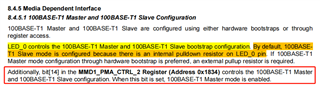
1. As the following figure says: "Master/Slave are configured using either hardware bootstraps or through register access." Does this mean that a hardware circuit configuration or a software register configuration can be selected?
a. So if the hardware circuit is configured as Slave (SM keep floating), can it still be configured as Master via software?
b. So if the hardware circuit is configured as Slave (SM pull down), can it still be configured as Master via software?
c. So if the hardware circuit is configured as Slave (SM pull up), can it still be configured as Master via software?
2. If the software is configured with the above mode at initialization, how can we confirm that the configuration was successful? Or what registers can read back?
a. For Master/Slave, how do the read the confirmation status?
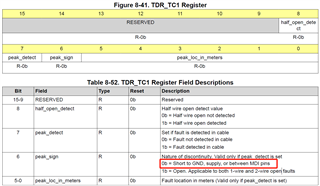
b. For Test mode0\1\2\4\5, how do the read the confirmation status?
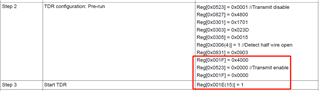
c. In TDR Testing Procedure, is Step 1(Write Reg.[0x1834] = 0x8001) mandatory regardless of Master/Slave mode?
After Step1, they need to wait for more than 1s for Step2(TDR configuration: Pre-run) register write?
Regards,
Ivy