This thread has been locked.

If you have a related question, please click the "Ask a related question" button in the top right corner. The newly created question will be automatically linked to this question.

DS90C032QML: LVDS Failure Protection

Part Number: DS90C032QML
Other Parts Discussed in Thread: THVD2412, ISO3080, ISOW1412

Tool/software:

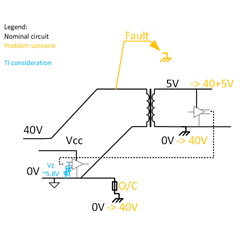
Hello, my organisation has a question about LVDS transceivers which we are using. We have several failures owing to their common-mode weakness. Due to mishandling the system cables, the receiving and transmitting ends find their grounds at significant voltage differences (20-40V) and it results in fried transmitters (DS90LV031AW-QML) and/or receivers (DS90C032E-QML). At system level this causes painful disassembly and repair across multiple modules. Typically aside from loss of function, we see 100-200 mA increased supply current per IC.

Accidents happen. Are there ways to strengthen against such problems: placing resistors, diodes or current limiters to control it?

Does TI have experience understanding the failure mechanism of excess common mode difference?

While I can't provide schematics, the Vcc would be 5, with positive biasing by e.g. 3k-100R-1k on the receiving side.

regards,

Chris

  • Hi Chris,

    I apologize for the delay here.

    So in general to protect the devices the bus pins must be within -0.3V to 5.8V to prevent damage. Those are the abs. max ratings. 

    Loss of function during these faults are unavoidable but in general we'd suggest some type of protection device - my main concern is that you won't have a ton of head room because we are typically looking at at least 3.8V as a typical VOH on the differential bus pin - so you need to keep the diode from conducting during normal operation but can't have it clamp above 5.8V.  Also if the fault is sustained you would need some type of resetable fuse or TBU because the diodes are only for transient protection generally speaking. 

    I am going to loop our protection device team into the thread to see if we have a specific part that we suggest - in general I'd suggest something extremely low capacitance due to the interface type - but I am not sure if we have anything that is going to protect the device during fault conditions. Series resistances between diode and receiver input aren't terrible ideas - but they can add attenuation to the signal - usually we'd suggest 10 ohm pulse proof resistors if added. 

    Protection device team - do we have any low capacitance diode that won't conduct at 4V but can keep overall clamped voltage below 5.8V? 

    Best,

    Parker Dodson

  • Hello Parker, thanks for the response. By diode, you mean a TVS/zener etc from ground to Vcc pins, right?

    More necessary background: we use LVDS to communicate without compromising single-point-ground philosophy (primary power subsystem and secondary, for all load subsystems) with one single point ground reference. In our instance the fused ground link gets broken by the raised ground potential, the same as destroys the devices. Since the surge is on ground, not on the Vcc, such suppression might miss the point?

    Considering something on the data lines, or on the ground pin.

    One helpful point is that these are not high frequency data signals but low frequency on/off level commands. 10kHz accurancy would do, so some capacitance might be tolerable.

  • Hi Chris, 

    An ESD/TVS diode might not work in this case if the overvoltage condition is for a long period of time, they are only rated to clamp transient events like ESD/Surge. A ~5V Zener diode with a tight tolerance would be better since they are designed for constant conduction, we don't have any in our portfolio but you might be able to find one at a distributor like digikey. 

    Regards,

    Sebastian 

  • Hi Sebastien, thanks. To be clear, I could share a diagram of nominal circuit. I see how it would protect the receiver, but hte transmitter would still be driving a zener at much lower voltage.

  • Hi Chris,

    Apologies I’m still looking into this since I’m not that familiar with LVDS.

    Could you use a Zener with a Vz above the nominal signal range on the transmitter side as well? 

    Regards,

    Sebastian

  • Hi Sebastian, okay. If we have 2x 5V zeners (one at each end), we need a resistor to limit the current/take the remaining potential difference. It can only go in the signal line itself. Then:

    - How can we size that resistor, based on the LVDS transmitter output capability, so that it doesn't disrupt normal operation?

    We also need a diode to clamp the 40V ground on transmitter side. At 40V it's also a source.  

    - Adding R and D to the transmission line will limit bandwidth - how do we calculate that?

    thanks,

    Chris

  • Hi Chris,

    Adding these zeners alone would attenuate your signal quite a bit since they have really high capacitance, and adding current limiting resistors would further worsen your signal integrity.

    From a protection diode perspective there doesn't seem to be an ideal solution here. It might be easier and more cost effective to use an interface that allows for a larger common mode range. 

    I will let parker from TRX comment since he will have better insight.

    Regards,

    Sebastian 

  • Hi Chris,

    What speed is your signal - and do you need the military qualification. 

    The reason I am asking is because I think there may be some mismatch between the interface chosen and what you need. LVDS devices are going to be relatively sensitive and it doesn't seem that we have one with a realistic protection device that will help with the end goal. The high 40V is really where the issue is going to come into play.  Depending on what you need - we may be able to pair you with a similar, but different interface that handles these stronger voltage issues better. If you need the speed of LVDS/M-LVDS or other system requirements mandate LVDS/M-LVDS usage  we may not have a great solution here. 

    Best,

    Parker Dodson

  • RS-485/RS-422 transceivers can tolerate higher ground offsets (the THVD2412(V) has a common-mode range of ±25 V), and are more robust (±70 V fault protection).

    If you require the communication to work correctly with a 40 V offset, then you need an isolated transceiver, e.g., ISO3080, or ISOW1412 with integrated power.