


Part Number: THVD2450V-EP
Tool/software:
I am using the THVD2450VDRCREP RS-485 transceiver in my design and I have a few questions regarding the recommended external components and control logic:
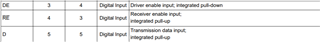
1. Internal vs External Pull Resistors:
The datasheet mentions that the DE, RE and DI pins have internal pull-up/down resistors. However, the application and layout guidelines suggest adding external resistors.
Is it mandatory to add external pull-up/down resistors if internal ones already exist?
In which conditions would the external resistors become necessary?
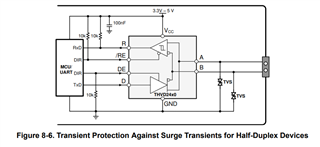
2. Series Resistors on A/B Lines:
Can I add series resistors (say, 10–33Ω) on the A and B differential lines for debugging or signal integrity tuning purposes?
Will this affect RS-485 communication compliance or performance?
3. Controlling DE and RE Together:
Can I control both DE and RE using a single GPIO from an MCU?
