This thread has been locked.

If you have a related question, please click the "Ask a related question" button in the top right corner. The newly created question will be automatically linked to this question.

TPD2E009: Diode Test Results Seem Odd

Part Number: TPD2E009

Tool/software:

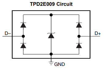
I am doing some 'diode tests' with a DMM on components on a PWA.  I was getting some weird values so I isolated the TPD2E009 component from the rest of the circuitry.  That appears to have made the values even weirder.  

From what I can tell, putting the probe from D+ to D- and vis-versa should read OPEN in both directions.  However, I am getting:
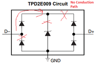
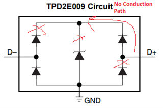
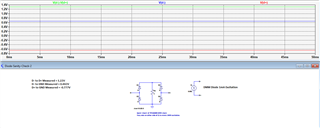
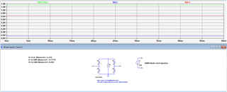
D+ to D- = 1.2V

D- to D+ = 1.2V

GND to D+ = 0.78V

D+ to GND = OPEN

GND to D- = 0.78V

D- to GND = OPEN

Does this seem correct?  Or is this a sign that there is transconductance/damage to one or more of the diodes within the TPD2E009?

  • Hi Elias,

    I don't think there are any abormalities here, a handheld DMM is typically only used to measure a forward voltage drop. If the diode were damaged you would see a short from the input to GND and GND to input. 

    ESD diodes are typically used in reverse bias, and will need a voltage at/above the breakdown voltage applied to allow large currents to flow from the inputs to GND (D+/- to GND). 

    When measuring a unidirectional ESD diode from GND to the input, you will see a typical forward voltage drop of ~0.7V. 

    Regards,

    Sebastian

  • Yes, and the GND to D+/- part makes sense measurement wise.  The issue I am having is why I am reading a value of 1.2V instead of 'OPEN' between D+ and D-. Looking at the datasheet, it seems like that shouldn't be possible as well as when I do a quick simulation in spice.  

    Diodes can fail open and short ..... but they can also fail in a way that lets a larger voltage value through them indicating that they are 'mostly failed' and allowing conduction from both directions.  I am wondering if I am observing a component that is 'on it's way out' but hasn't failed all the way yet.

  • Hi Elias,

    Based on the equivalen circuit it is possible to measure a voltage above the typical diode drop from D+ to D- if current is flowing from D1 to D2. 

    A leakage current check is typically what is used to check for a damaged part, if it's outside of the 0,1uA max this would indicate damage. 

    Regards,

    Sebastian 

  • Can you explain to me the current path between D- to D+ and vis versa with a DMM applying a 1mA diode test signal to show a voltage drop?

    I know a bidirectional TVS would read open on both sides due to having diodes facing both directions between the pins.  From the circuit above, it appears that diodes are in both directions between the two pins and would cause a DMM 1mA diode test to be seen as OPEN in both directions. 

  • Hi Elias,

    Unfortunately this is a legacy part on an older process, so we have limited information on the design. 

    Are you able to sweep voltage and measure current to do the leakage check? 

    Regards,

    Sebastian 

  • I don't believe I have anything that measures uA at the moment.  But I do know at min it is generating a voltage in both directions when 1mA is applied across the Data pins by a DMM. 

    ......Which would indicate that there is most likely an issue or the electrical schematic is incorrect in the datasheet.  

  • Is the GND pin floating when you're doing this measurement? 

  • The behavior is the same both with the GND pin floating or not floating.  

  • I am trying to also keep an open mind that I am thinking on this incorrectly and somehow this is possible under normal 1mA excitation conditions with a DMM....


    but I am not convinced at this time.  Which is why I am here for a sanity check. 

  • Did a couple more measurements and sim. Hopefully this helps explain some. 

    With all three pins physically isolated from circuit with a 1mA source from my DMM I get:

    D+ to D- = 1.2V, D+ to GND = 0.44V, D- to GND = -0.77V

    D- to D+ = 1.2V, D+ to GND = -0.77V, D- to GND = 0.44V

    If I simulate a 1mA injection with a working TVS in the center of the circuit it looks like this: 

    Typically DMMs only read a forward voltage up to ~2V when applying the 1mA and will otherwise say 'OPEN.' In this case I would expect the DMM to say 'OPEN' when measuring between D+/D-.

    If I simulate this with a shorted TVS in the center of the circuit it looks like this: 

    This is a lot closer to what I am physically measuring.

  • Hi Elias,

    I just received some new TPD2E009 units, and I'm measuring the same ~1.2V from D+/- with and without the GND pin floating. 

    I agree with your initial understanding of the conduction path, however that is just the simplified equivalent circuit of the actual structure. 

    I spoke with our design team and they mentioned this could be a parisitic BJT trigger happening.

    We don't have the design files so I don't have access to the exact structure, which would be under NDA anyway... but maybe this article can provide some insight: 

    Regards,

    Sebastian