Part Number: THVD2450V-EP
Other Parts Discussed in Thread: THVD2450V
Tool/software:
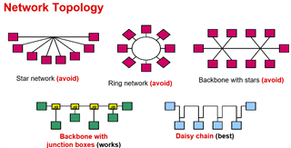
Hello, I am currently working on designing a system that comprises 7 subsystems. I intend to establish communication between these subsystems using RS485. They will be interconnected with 10-meter cables, resulting in a total bus length of approximately 70 meters. I have some questions regarding this system below. I would be very grateful if you could answer them.
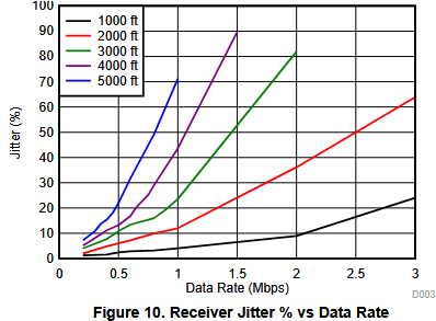
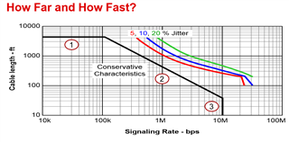
Q1: I expect my data rate to be approximately 2 Mbps. According to the RS485 standard’s speed-distance curve, I am pushing the limits. I understand the importance of the cable. Assuming I use a special shielded twisted pair cable with 120 ohms characteristic impedance, can I achieve 2 Mbps over 70 meters using the THVD2450V transceiver?
Q2: This IC can be powered by either 3.3V or 5V. As I understand, the differential output voltage of the driver changes depending on the supply voltage. Considering all 7 subsystems in the system will have the same transceiver, does the supply voltage affect the achievable distance and data rate? Which voltage should I choose?
Q3: Besides establishing reliable communication, I also need to pass EMC-EMI tests. This IC has relatively fast rise and fall times, which can increase EMC problems. How can I reduce the rise-fall times without compromising system integrity? Or do you have any suggestions or key focus areas regarding EMC and EMI?
Q4: Independently of this application, sometimes the driver and receiver are implemented as separate ICs rather than integrated into one. What could be the advantages and disadvantages of using separate driver and receiver ICs?
Best regards