Part Number: TUSB212
Other Parts Discussed in Thread: TUSB216, TUSB214
Tool/software:
Hello TI Teams:
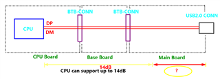
如下是我们USB2.0的走线图,跨了3块PCB,PCB之间用BTB连接器桥接。
由于CPU最大允许插损是14dB,所以从14dB处到USB2.0 CONN,需要用TUSB212中继以提高增益。
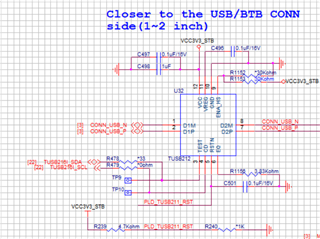
如手册建议的“suggest to place the TUSB212 closer to the USB CONN side(1~2 inch)”,则TUSB212的位置超出了CPU要求的14dB的位置。
Q1. 基于上面这种情况,帮忙看看有什么好的办法解决呢?
Q2 如果靠近USB CONN放置一颗TUSB212,在中间路径上再放置一颗TUSB212是否可行?即同一条USB高速线上使用2颗TUSB212。
Thanks!