Other Parts Discussed in Thread: TDP1204, TMDS1204, TMUXHS4212, TMDS181, TMDS1204EVM
Tool/software:
Dear Team,
I ned to know the reflow soldering profile for SN65DP159RSBT.
The graph of Time vs Temp.
Regards,
Irfan
This thread has been locked.
If you have a related question, please click the "Ask a related question" button in the top right corner. The newly created question will be automatically linked to this question.
Tool/software:
Dear Team,
I ned to know the reflow soldering profile for SN65DP159RSBT.
The graph of Time vs Temp.
Regards,
Irfan
Also whether there is any other retimer which can support HDMI 2.1
Hi,
Please see this app note for the solder profile. Unfortunately we do not have a HDMI2.1 re-timer in our product portfolio.
Thanks
David
Irfan
Irfan
Both TDP1204 and TMDS1204 do support HDMI2.1, but they are re-driver, not re-timer, also they are not pin-to-pin compatible with DP159.
Thanks
David
Hi David,
Which one should i useTDP1204RNQR or TMDS1204RNQR for re-driver side and confirm me whether I can use which one for both source and sink.
Thanks,
Irfan
Irfan
Both TMDS1204 and TDP1204 can support source and sink design. The main difference between the two is the feature set as shown below.

So you can choose between the two depends on your system design requirement.
Thanks
David
Hi David,
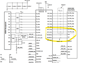
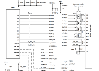
Why doesn't the source side application requires a switch for either clk or FRL data.
Below mentioned is for sink side, why actually it is required in RX side and not in TX side.
Do we have to add an external switch for that or is it not necessary.
Thanks,
Irfan
Hi David.,
There are 2 method of implementing HPD can we go with the previous HDP implementation.
Where sink side HPD is connected to HPD IN and HPD OUT will be connected to connector by below mentioned circuit.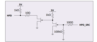
Can you please confirm me this once.
Thanks,
Irfan
Irfan
Please see my response below.
Why doesn't the source side application requires a switch for either clk or FRL data.
Below mentioned is for sink side, why actually it is required in RX side and not in TX side.
Do we have to add an external switch for that or is it not necessary.
Majority of sources and sink can support switching between the CLK (HDMI1.4/2.0) and FRL (2.1). In this case, no external MUX is required. If the source and sink have separate CLK and FRL, then you would need an external MUX such as TMUXHS4212 to switch between them depending on the HDMI1.4/2.0/2.1.
There are 2 method of implementing HPD can we go with the previous HDP implementation.
Where sink side HPD is connected to HPD IN and HPD OUT will be connected to connector by below mentioned circuit.
Please refer to Figure 35 TMDS181 sink side application for the HPD implementation.
Thanks
David
Hi,
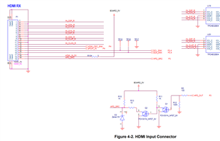
Can the same HPD method can be used for TMDS1204 as used in TMDS181.
For Source side can the RCLK can be used depending upon HDMI1.4/2.0 and outclk for FRL ?
Thanks,
Irfan
Irfan
Please see my response below
Can the same HPD method can be used for TMDS1204 as used in TMDS181.
Yes, and this is how I did on the TMDS1204 EVM as shown below. The HPD_OUT is the HPD output from TMDS1204.
For Source side can the RCLK can be used depending upon HDMI1.4/2.0 and outclk for FRL ?
The RCLK is an output only and it is only for HDMI1.4 and 2.0, so I am curious how you want to use RCLK for FRL, do you have a block diagram to show the proposed implementation?
Thanks
David
Hi,
1) While sending the TX HDMI 2.1 all the data can be out from D0-D2 and 4th data from Out CLK , but when it is HDMI 2.0 I mean when it fall back to HMDI 2.0 then data will be out from D0-D2 and can the remaining i.e. CLK can be sent through Out CLK or RCLK?
2) What to do with SIGDET pin when not used ? Can be left floating?
3) Can you please verify the attached image for pin-strap mode and also help me with the Default mode of each pin.

Thanks,
Irfan
Irfan
1) While sending the TX HDMI 2.1 all the data can be out from D0-D2 and 4th data from Out CLK , but when it is HDMI 2.0 I mean when it fall back to HMDI 2.0 then data will be out from D0-D2 and can the remaining i.e. CLK can be sent through Out CLK or RCLK?
When the fan-out buffer feature is enabled, the TMDS1204 will output the HDMI clock on RCLKOUTp/n when operating in HDMI 1.4 or HDMI 2.0. The OUT_CLKp/n will be disabled. When operating in HDMI 2.1 FRL mode, the TMDS1204 will output FRL data3 on OUT_CLKp/n. RCLKOUTp/n will be disabled.
2) What to do with SIGDET pin when not used ? Can be left floating?
You can leave it floating
3) Can you please verify the attached image for pin-strap mode and also help me with the Default mode of each pin.
Please see this implementation guide on recommended pin strap setting.
Thanks
David
Hi David,
Thanks for the response.
Can you please tell me whether the current consumption of the TMDS1204 IC ?
What value should be of the pull up resistor when AC coupled for sink application at output? I have put 49.9E . Attached image for your reference
Thanks,
Irfan
Irfan
Please see below for the power consumption number.
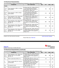
With TMDS1204 output supporting both AC and DC coupling, you do not need the 49.9ohm termination to 3.3V. For AC coupled output, please set AC_EN pin high.
Thanks
David
David,
Can you recommend what should I consider the supply current for TMDS1204 that it supports HDMI 2.1, HDMI2.0 and HDMI 1.4.
* For which my Sink is AC Coupled and Source is DC coupled
Thanks
Hi,
1220mW is the max power dissipation for TMDS1204, so 1220/3.6= ~338mA. So I would use ~400mA for both the source and sink design.
Thanks
David
Hi David,
Can you please review my schematics attached.
1) Please verify the pin strapping.
2) Whether it can support both HDMI 2.1 and HDMI 2.0.
Thanks,
Irfan
Irfan
Please see attached for my review comment.
TI REFERENCE HDMI 2.1_TI_Reviewed_06242025.pdf
Thanks
David
David,
Whether the 2nd page of the schematics is reviewed and it doesn't have any issues?
And for the source side is CMC is must or we can not add it in our design?
What about the mode pin? whether 20K pull down for fan out buffer supported is ok?
Can you please share me the layout for the TMSD1204 EVM?
Thanks,
Irfan
Irfan
Please see attached for my review comment on the 2nd page of the schematic.
2870.TI REFERENCE HDMI 2.1_TI_Reviewed_06242025.pdf
For sink side design, MODE = "R" means adaptive equalizer with fan out buffer enabled, so it looks to be correct.
Thanks
David
Hi David,
Thanks for the review comments.
Request you to send the Layout for the TMDS1204 EVM.
Also can you mention the operating temperature of the TMDS1204.
Thanks,
Irfan
Irfan
For the TMDS1204, the operating temperature is 0 to 70C.
For the TMDS1204I, the operating temperature is -40 to 85C.

Would you please accept my friendship request so I can send you the TMDS1204EVM layout file?
Thanks
David
David,
Do the TMDS1204 IC has any pin delay for which I have to consider for layout.
I have accepted the request.
Thanks,
Irfan
Irfan
The propagation delay going through the TMDS1204 will be very small comparing against the propagation delay of the PCB trace, so you do not need to consider it for the layout. Please see below for the TMDS1204 layout guide.
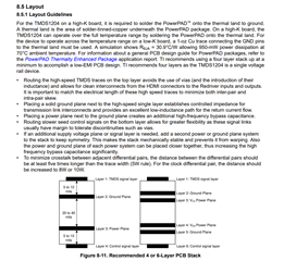
I sent you the TMDS1204 EVM board file, would you please check?
Thanks
David
Hi David,
Thank you David, but can you tell me what will be the pin delay of TMDS1204.
Regards,
Irfan
Irfan
The propagation delay at TTP4 is min of 90ps and max of 220ps.

Thanks
David
David,
1) What does TTP4 means, and what should i consider the typical value of delay.
2) In previous HDMI 2.0 the data lines along with the clock line we used to group length match it together, now that the HDMI 2.1 has data integrated with clock and also there is an RCLK_OUT out pin in TMDS1204 re-driver whether we need to do the group length matching along with the D0-D3 data lane or length matching for D0-D3 is enough? Is it required for
Regards,
Irfan
Irfan
Please see below for the TTP4 definition. From our lab measurement, the typical value is around 160ps.
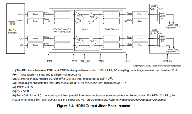
I would group length matching D0-D3 and RCLK_OUT pin.
Thanks
David
David,
Is Genlock required for HDMI 2.1, and can you please tell me how does that work in this TMDS1204.
How does the RCLK_OUT is used in VEK280 for Gen lock.
Regards,
Irfan
Irfan
I am not familiar with AMD VEK280 design to answer this question, please reach out to AMD for support on their Gen lock implementation.
Thanks
David
David
Can you please tell me if you have any reference or how to implement the Genlock.
Thanks,
Irfan
Irfan
Since Genlock is part of the AMD VEK280 design, please see this link to register and download the VEK280 schematic.
Thanks
David