This thread has been locked.

If you have a related question, please click the "Ask a related question" button in the top right corner. The newly created question will be automatically linked to this question.

TPD4E05U06: HDMI output does not work.

Part Number: TPD4E05U06
Other Parts Discussed in Thread: TPD1E05U06, , ESD224

Tool/software:

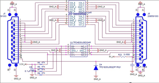
We designed a board that connects HDMI to HDMI between a PC and a monitor.

We applied the Protection IC, but the HDMI connection is not working.

The TMDS line has 100 ohm impedance.

Currently, HDMI Pin 17 is NC on the circuit, but even if we connect GND, the image does not appear.

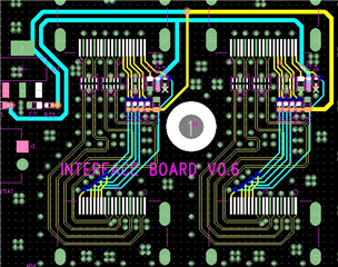
The circuit diagram shows that the right side of the HDMI Port is the Monitor side, and the artwork is on the top side of the Monitor side.

Please review.

  • Hi, 

    Just a few questions, are you plugging the board into an HDMI port on both the PC and monitor? Also, have you tried removing the diodes to see if the board works? Nothing on the schematic or board jumps out at me as being incorrect.

    Best,

    McKenzie

  • Hello. 

    Thank you for your reply.
    Yes, I connected both the PC and the Monitor.
    When you say diode, do you mean D4?
    Even after removing D4, the image still does not appear.

    Best Regards

  • Hi, 

    By removing the diodes, I meant all so ESD224, TPD4E05U06, and TPD1E05U06. Would it be possible to send the board files so I can go through it?

    Best,

    McKenzie

  • Hello.

    There are boards that do not have ESD Protection ICs, but they have the same symptoms.
    I have one question.
    I understand that there should be a gap of 1.2mm or more between TMDS lines.
    The gap between the TMDS lines on the HDMI Connector side of the PC is 0.8mm. Could this be the problem?

    Best Regards

  • Hi Sincheol,

    While the gap between traces could affect the signal I'm not sure if it would completely kill the image. I would expect to at least see a corrupted image or some noise instead.

    Since the board still does not work after removing the ESD diodes, this sounds like a layout or manufacturing issue. If you have access to a logic analyzer or oscilloscope, have you checked that the data is being sent properly across the board? Alternatively, have you checked continuity from connector to connector with a multimeter or similar tool? 

    Best,

    Chris

  • Hello. Chris Pui,

    I checked with a multimeter, but there was nothing unusual.

    I couldn't find any problems on the PCB.

    It will cost money, but I plan to remake the board with a distance of 1.2mm or more between TMDS.

    It doesn't seem easy to find a proper method at the moment.

    Thanks.

    Mr. Kang

  • Hi Mr Kang, 

    Please keep us updated if you have more questions. Since there is no difference in performance when the diodes are placed and when they are not, I expect it to be a layout issue. 

    Best,

    McKenzie

  • Hello. McKenzie,

    OK. I respect your opinion.
    First of all, I checked that the board using a different type of connector works, so I expect it to be a problem with the spacing of the TMDS lines. I would like to ask if I can request a review after proceeding with the artwork.

    Best,

  • Hi Mr Kang, 

    Yes, I can review after you finish. Feel free to reach out on E2E or email me (m-eaker1@ti.com). 

    Best,

    McKenzie