This thread has been locked.

If you have a related question, please click the "Ask a related question" button in the top right corner. The newly created question will be automatically linked to this question.

LMG2100EVM-078: Dead-Time Generating Circuit

Part Number: LMG2100EVM-078
Other Parts Discussed in Thread: SN74LVC2G14, SN74LVC3G14

Tool/software:

hi team,

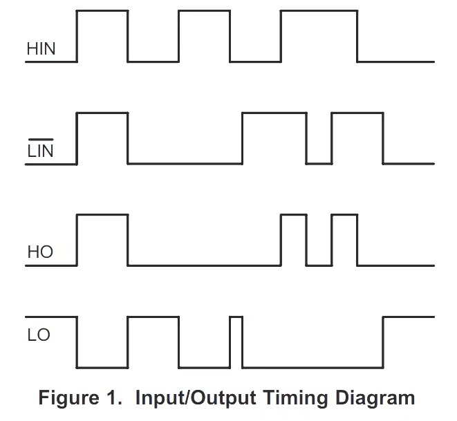
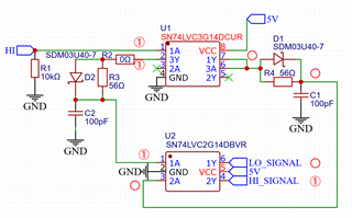
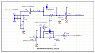
 i want to check the dead time circuit why will using SN74LVC2G14 + SN74LVC3G14 inverter for dt control, why not just use a 6 channel inverter directly?

 tks for the insight here.

  • Hello Allen,

    When we were designing the circuit we choose separate triple channel and a dual channel trigger for design convenience and availability and it satisfies our functional requirements.

    That said, using a 6 channel Inverter is also feasible and can be used if it is serving the purpose to Invert the signal and adding buffer to the signals and also if the application is calling for a tighter integration or reduced component count.

    Kindly reply back for anymore concerns.

    Regards,

    Adithya

  • hi Adithya,

     we aim to set as the below dead time logic , and i found  the lmg2100 evm have similar feature .only a pwm input and generate a complementary pwm too.

    is there any difference with 6 inverter for dt control compare if you use separate triple channel and a dual channel trigger  at the beginning.?

  • Hello Allen,

    Thanks for the reply, 

    Can you please share the 6 channel inverter part number that you are planning to use and also from where the Timing diagram is taken from?

    Having these information can help me to analyze it better.

    Regards,

    Adithya Ankam

  • hi Adithya ,

     I am trying to reproduce the SCH base on the EVM design file. 

    in this design, there is only need one PWM input and will output 2 HI/LO signal.

    ideally, i think 2 inverter channels already work, so why add another 2 channels inverter at the end of signal? 


  • Hi Allen,

    I understood your concern over here. our LMG2100EVM board Deadtime control circuit is designed in such a way that it can work in 2 ways.

    Case 1: To generate 2 complementary pulses from a given PWM pulse

    Case 2: By removing R11, R12 and connecting R13 we can make the it to generate 2 individual HI and LI pulses.

                  By this way we can make give separate HI,LI pulses and generate HI and LI signals.

    Considering your case, you don't need to have the U2 inverter.

    Just a 3 channel inverter should work for your case.

    Regards,

    Adithya Ankam