Part Number: SN65DSI84
Other Parts Discussed in Thread: DSI-TUNER
Tool/software:
Hi team,
The customer used the following E2E link debugging DSI Tuner software and found the following problems:
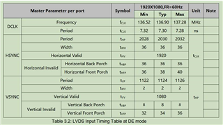
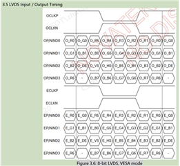
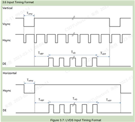
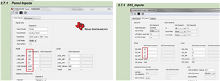
1. In the DSI-Tuner documentation example, why are the LVDS timing and DSI timing settings different? See the figure below.
How do I set these two?
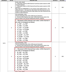
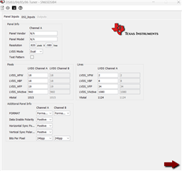
2. After installing the DSI-Tuner tool, the interface is different from that in the document (the left picture below is the document picture, and the right picture is the newly installed interface). The clk in the red box in the picture below cannot be set;
How to solve it?
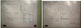
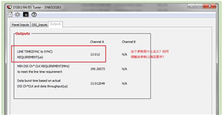
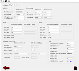
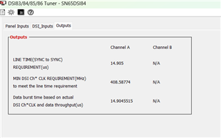
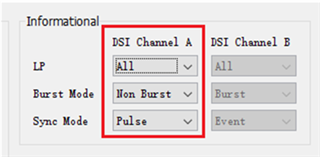
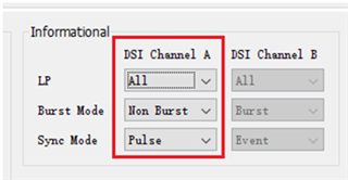
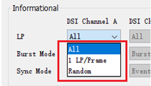
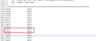
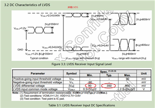
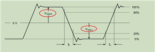
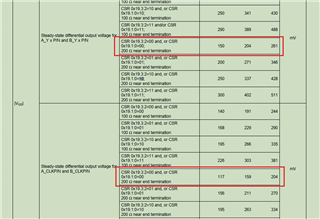
3. What do the parameters in the red box in the figure below mean? How should they be set to ensure that the parameter requirements are met?