This thread has been locked.

If you have a related question, please click the "Ask a related question" button in the top right corner. The newly created question will be automatically linked to this question.

TUSB321: Probably not working correctly

Part Number: TUSB321
Other Parts Discussed in Thread: TUSB320EVM

Tool/software:

Hello support, 

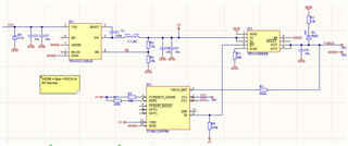
I designed very simple 5v usbC source with TPS563212DRLR buck converter.

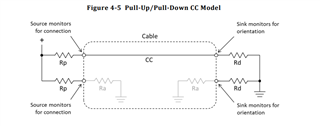
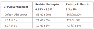
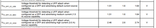
CC channel is controlled with TUSB321. CURRENT_MODE = 10k pullup, PORT = 200k pullup.. With ID pin the load switch is controlled. From usbC cable I connect the yellow wire to only CC1pin. CC2 is not use.

Load switch TPS2556DRBR. ILIM resistor = 40k

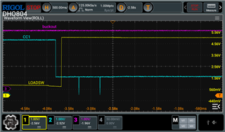
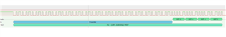
The device works. But in my opinion not properly. Because my mobile is charged only with 5W, so 1A. And I set the CURRENT_MODE to 3A. When I connected usb PD charger with 5V/3A support the mobile phone request on CC communication 5v/3A from source. Below is the screenshot what my mobile request from USB PD source adapter.

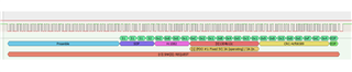
Also, I tried to decode the TUSB321 CC line with USB PD decode but this is not available, right?

Any suggestion? 

Thank you

Martin

  • after connecting the sink device the voltage on the CC pin is 1.744V

    Without sink device the voltage on CC pin is 4.86V

    Also, I tried to disconnect the 10k resistor from CURRENT_LIMIT pin of TUSB321. So, then the pin was floated and should report 500mA. The voltage on the CC after the sink was connected = 0.5V. That's correct, right?

    Or there is maybe problem with UBC-C cable which I soldered on my board? I mean that, the manufacturer add some fake resistor in the cable?

    Or the problem with the mobile phone charging can be because it want to detect BC1.2? 

    testing with xiaomi 13Lite

  • Hi,

    Probably, I found the problem, but I don't understand why this happen. Below is the screen of Loadswitch output when the load is 1.8R  -> 5/1.8= 2.7A

    Voltage on the buck converter output is still 5.1V.

    I change the loadswitch ILIM resistor to 30k but still happen the below issue.

    Loadswitch enable is still LOW, so the loadswitch is enabled during below error. So the error is overcurrent protection?

    UPDATE:

    Found the solution with load switch - Probably bad soldering. I re-solder it and it can't go to OCP.

    But the issue with charging the mobile phone is still there. CC voltage is 1.77V and only 5W the phone takes.

  • Hi Martin,

    Just to check, is the TUSB321 connected to the Xiaomi phone at start-up, or is the TUSB321 unconnected at start-up?

    Is there any way to test with both CC1 and CC2 connected to the Type-C connector, to ensure that only using one CC pin is not the issue?

    Also, I tried to disconnect the 10k resistor from CURRENT_LIMIT pin of TUSB321. So, then the pin was floated and should report 500mA. The voltage on the CC after the sink was connected = 0.5V. That's correct, right?

    Yes, I believe that should be correct. When there is a correct connection over the CC lines, the CC line should be pulled down to ground via RD, like the diagram above.

    Could you monitor the CC pin voltages as well? Depending on the level of CURRENT_MODE, the CC pin voltage should change. Also, this is just with a typical type-C cable and not an active cable, correct?

    Thanks,

    Ryan

  • Hello Ryan,

    Yes, I am using standard cable with only one CC wire. So, the cable is not active. Without VCONN support.

    Just to check, is the TUSB321 connected to the Xiaomi phone at start-up, or is the TUSB321 unconnected at start-up?

    How you mean this?

    When the Xiaomi phone is not connected, the voltage on CC line is around 4.8V. That's okay, because on TUSB321 side are pullups. Currently, I have connected 10k pullup to CURRENT_MODE pin of TUSB321. After connecting the phone to usbC cable the voltage on the CCline change to approximately 1.68-1.77V. This voltage reporting 3A capabilities.

    And I don't understand why Xiaomi phone and also 2 other phones test phones are charging with 5W only.

    Is there any way to test with both CC1 and CC2 connected to the Type-C connector, to ensure that only using one CC pin is not the issue?

    This is not possible. I don't have test pad connected to second CC2 pin of TUSB321. My board is extremely small (13x8.4mm). Also, in usbC-usbC cable is only one CC wire so, I cannot connect both CC pins of TUSB321. Only active usbC cables have two CC wires in cable. One for CC communication, and second one for VCONN. 

    Also, I tried to rotate the connector in phone usbC port, but this this not help.

    Thanks for help.
    Best regards,
    Martin

  • Hi Ryan,

    Below I am sending scope screen when mobile was connected. Power supply reporting 5W load.

  • Hi Martin,

    Just to confirm your setup, You have your board with the TUSB321, and is it connecting directly to the Xiaomi phone, or do you have another device in the middle of the two devices? If there is a device in the middle, is it possible to connect your board directly to the Xiaomi phone and make sure it is not interfering?

    As long as the TPS2556DRBR Can support 5V/3A, which it looks like it can, then I don't see any issue with that being used in combination with the TUSB321.

    Can you use the CC analyzer to capture the TUSB321 is advertising 5V/3A, the Xiaomi phone is requesting 5V/3A, and the negotiation taking place to confirm 5V/3A is delivered?

    How you mean this?

    When the Xiaomi phone is not connected, the voltage on CC line is around 4.8V. That's okay, because on TUSB321 side are pullups. Currently, I have connected 10k pullup to CURRENT_MODE pin of TUSB321. After connecting the phone to usbC cable the voltage on the CCline change to approximately 1.68-1.77V. This voltage reporting 3A capabilities.

    I mean that when you power your board with the TUSB321, is the Xiaomi phone connected to your board, or do you wait for your board to be powered before connecting the Xiaomi phone?

    My suspicion right now is that while the TUSB321 should be correctly advertising 5V/3A, something at the Xiaomi phone or in between is causing either the negotiation to fail, or causing the TUSB321 to not see a request for 5V/3A, resulting in the default 5V/900mA.

    Thanks,

    Ryan

  • Hello Ryan,

    Thank you that you are getting back.

    My board with TUSB321 is connecting directly to xioami phone. 

    I tried to decode the CC but this is result. Seams like there is problem somewhere.

    There are two attempts of communication:

    Both report same. First:

    Second:

    What this PD message mean? I don't google it yet.

    I mean that when you power your board with the TUSB321, is the Xiaomi phone connected to your board, or do you wait for your board to be powered before connecting the Xiaomi phone?

    Firstly, I power up the board with TUSB321 and then I connect the xiaomi phone.

    My suspicion right now is that while the TUSB321 should be correctly advertising 5V/3A, something at the Xiaomi phone or in between is causing either the negotiation to fail, or causing the TUSB321 to not see a request for 5V/3A, resulting in the default 5V/900mA.

    Sure, this sounds real. I have one onsemi EVB with type-C controller. I will try to test it with it. I will try to configure the EVB ask 5V sink.

    My board. TUSB321 on the bottom side

    Best regards,
    Martin

  • Hi Martin,

    Sure, this sounds real. I have one onsemi EVB with type-C controller. I will try to test it with it. I will try to configure the EVB ask 5V sink.

    Testing with EVMss to make sure those work would be good, I agree. I would also recommend looking at the TUSB320EVM, that should have similar performance to the TUSB321.

    The board you are using is much smaller than I anticipated, I'm guessing the only connections to the cable are VBUS, GND, and CC1? Is VBUS being provided by an SOC, or just a 5V rail on your board?

    I tried to decode the CC but this is result. Seams like there is problem somewhere.

    There are two attempts of communication:

    Both report same. First:

    Second:

    What this PD message mean? I don't google it yet.

    I'm not fully familiar with this either, but I don't believe this should be what appears, there should be a proper handshake process going on. I will look in the background to see if I can find an example of a successful handshake.

    Thanks,

    Ryan

  • Hi Ryan, 

    The board you are using is much smaller than I anticipated, I'm guessing the only connections to the cable are VBUS, GND, and CC1? Is VBUS being provided by an SOC, or just a 5V rail on your board?

    Yes, only VBUS, GND and CC line wire is connected. I don't need D+ and D- so I cut it out. 

    How you mean if VBUS is provided by an SOC? 

    Check the schematic upper. Cable is connected to the loadswich output. Buck converter is connected to banana pins. 

    Regards, 

    Martin

  • Hi 

    With EVB looks that it is working correctly.

    Thanks
    Martin

  • Check below:

    This is usbC port config on EVB

    After connecting my board you can see that EVB port is connected as a Sink and reported current from source is 3A.

    Also, another test with my another board with IC - TPS25821DSSR. CHG pin = HIGH. So, it is correct that source report 1.5A

  • Hi Ryan,

    I probably found what do the problem with charging the xiaomi phone

    I found a way how to reproduce on the EVB with FUSB307B the error with HRST command on CC line.

    1. When I configured the EVB as a Sink with USB PD disable and after connecting the board with TUSB321 -> everything works, without HRST command.

    2. When I configured the EVB as a Sink with USB PD enable and after connecting the board with TUSB321 ->  HRST command appeared on CC line.

    What do you think about this? Is it possible that you or the product engineers will try to test this behavior?

    Thanks
    Martin

  • Hi Martin:

       Ryan is out today and will be back on next Monday.

    Best

    Brian

  • Hi Ryan,

    Hope you have a great weekend. I want to inform you, that I tested the BC1.2 today. This works correctly with xiaomi and other phones. Phones was charging with 7.5W(1.5A).

  • Hi Martin,

    So when using BC1.2, there's no issue with using your board, but when trying to use something with USB-PD, the issue is present?

    The TUSB321 doesn't support any USB-PD functionality, and only supports what is allowed in the USB type-C spec for power draw via CC negotiation, I.E 5V/900mA, 5V/1.5A, and 5V/3A. It could be that one device is attempting PD negotiation, and our TUSB321 does not support it, resulting in the default setting on 5V/900mA.

    I'm not 100% sure this is something we could test in our lab, as our team does not support any USB-PD devices or testing, but I can double check that.

    Thanks,

    Ryan

  • Hi Ryan,

    Thank you for your feedback.

    So when using BC1.2, there's no issue with using your board, but when trying to use something with USB-PD, the issue is present?

    Yes, I noticed the HRST error and limitation the output current to 500mA only when I tried to connect TUSB321 with USB-PD sink.

    The TUSB321 doesn't support any USB-PD functionality, and only supports what is allowed in the USB type-C spec for power draw via CC negotiation, I.E 5V/900mA, 5V/1.5A, and 5V/3A. It could be that one device is attempting PD negotiation, and our TUSB321 does not support it, resulting in the default setting on 5V/900mA.

    I understand this and I think this is true. Is this behavior same for all your CC logic controllers? Can you check it with your team?

    But then the CC logic controller is quite useless :D because nowadays most of devices support USB PD for fast charging - let's say 15-30W. And 15W charging is mostly supported by 5V/3A.

    Then, what is the purpose of the CC logic controller when it cannot trigger the USB PD controller to set 5V/3A? Then I can save money and just connect pullup resistor (Rp) on source side :D according to table below. And don't use CC logic controller.

    Imagine my situation. I want to design simple 5V USB-C charger which will meet the USB-C specification like: Active CC logic controller, VBUS load switch with current limiter etc. I want to support at least 2A, so according to USB-C spec I can choose 1.5A or 3A output.

    How to do it, if CC logic controller (TUSB321) is not able to trigger USB PD controllers and I don't want to do more complicated design with USB PD ICs which must be configured for example via I2C.

    Let's investigate more about this.

    Thank you for your interest in this.
    Martin

  • Hi Martin,

    I understand this and I think this is true. Is this behavior same for all your CC logic controllers? Can you check it with your team?

    But then the CC logic controller is quite useless :D because nowadays most of devices support USB PD for fast charging - let's say 15-30W. And 15W charging is mostly supported by 5V/3A.

    Then, what is the purpose of the CC logic controller when it cannot trigger the USB PD controller to set 5V/3A? Then I can save money and just connect pullup resistor (Rp) on source side :D according to table below. And don't use CC logic controller.

    The TUSB321, and any other CC controller we have, is also used to control when VBUS is sent via the ID pin. If VBUS is not controlled by the ID pin, which toggles based on the CC negotiation, then type-C functionality will be impacted, with either only one side working or no USB3 functionality in general.

    To me, it sounds as though the Xiaomi phone and the other phones you have tested may be detecting that the TUSB321 is advertising 5V/3A, but they may not be pulling that 5V/3A. Just because the TUSB321 is advertising 5V/3A doesn't mean the sink will automatically pull at that amount. The test phones may be set to pull a different amount, I'm not sure this is anything the TUSB321 would affect.

    Meanwhile, when you tested with the FUSB307B EVB with no USB PD, you saw no issues. From my understanding with USB-PD, in the CC negotiation process, first the sink will detect what current is advertised by the DFP and will pull the voltage/current it needs based on what is advertised. Then, after that, it will begin the USB-PD negotiation process to go past what is typically allowed in the Type-C spec via CC negotiation. This communication requires a PD controller of some kind on both sides, or else there will be no USB-PD functionality. Outside of this, only advertisement of voltage and current from the source and detection by the sink will take place over the CC line.

    The best way to confirm that it is not an issue with your board or our device would be to test with the TUSB320EVM, which should have the same functionality. Using I2C, you can set this device to advertise 5V/3A, and test to make sure that that EVM has the same performance as the TUSB321.

    Thanks,

    Ryan

  • Hi Ryan,

    Thank you for respond.

    When device not using the USB PD communication, then the Type-C controller measure the voltage changes on CC line which depending on pullup(source) and pulldown divider(sink). So, I thought that when USB PD controller didn't get any PD request then it start measuring the voltage changes on CC lines.

    Current behavior confused me, because:
    - The phone requested from PD charger 5V/3A
    - TUSB321 have configure the correct pullup and the voltage on CC line is around 1.68V. So, this reporting 5V/3A capabilities.

    The best way to confirm that it is not an issue with your board or our device would be to test with the TUSB320EVM, which should have the same functionality. Using I2C, you can set this device to advertise 5V/3A, and test to make sure that that EVM has the same performance as the TUSB321.

    Sorry, but the TUSB320EVM is so expensive. Or is it possible to send me it as a sample?

    Thanks
    Martin

  • Hi Martin,

    Current behavior confused me, because:
    - The phone requested from PD charger 5V/3A
    - TUSB321 have configure the correct pullup and the voltage on CC line is around 1.68V. So, this reporting 5V/3A capabilities.

    From my understanding in a typical CC communication, the sink will not send a request for 5V/3A. In a typical CC negotiation, if it sees 5V/3A advertised and it is allowed to pull that much, it will just begin to pull 5V/3A without sending a request or anything. In a PD negotiation, this is likely different.

    In a 5V/3A connection, the voltage on the CC line should be within the range specified by VTH_DFP_CC_HIGH. If you are seeing around 1.68V, the actual current being pulled is like 900mA or 1.5mA.

    Sorry, but the TUSB320EVM is so expensive. Or is it possible to send me it as a sample?

    If you have a local FAE, I would reach out to them. They can help with arranging a sample.

    Thanks,

    Ryan

  • Hi Ryan. 

    Looks that you are correct. I probably saw some wrong information on the internet about voltage level on CC line. 

    Also, how can I found who is FAE for my location (Slovakia)? I don't have experience with this. 

    Thanks, 

    Martin

  • Hi Martin,

    I've reached out to who I believe should be our contact for your company asking if they can help set up sending a sample, I will let you know what I hear back.

    Thanks,

    Ryan