This thread has been locked.

If you have a related question, please click the "Ask a related question" button in the top right corner. The newly created question will be automatically linked to this question.

DP83848C: Interface forum

Part Number: DP83848C

Tool/software:

Hi,

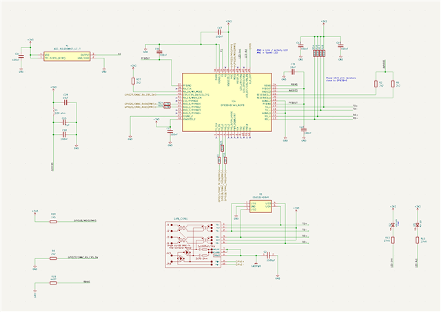
I’m working on a prototype which uses the DP83848C to interface to an ESP32 using RMII. At present I’m unable to configure the PHY start up with auto-negotiation enabled.

I use pins 26 and 28 to drive LEDs directly. Each LED is connected to 3V3 via a 274-ohm resistor. Pin 27 is not connected and relies on the internal pull-up resistor for the strapping value.

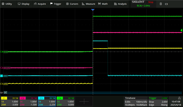
When the DP83848C starts up, it looks like the preferred forced mode value is 100 Half-Duplex.

By changing our network switch setting we can obtain an IP address and send / receive data at the following forced mode values.
10 Half-Duplex
10 Full-Duplex
100 Half-Duplex
100 Full-Duplex

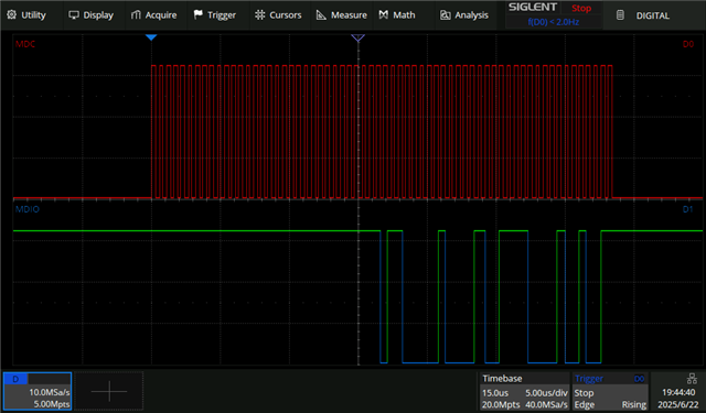
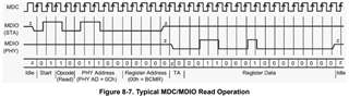
From the trace there seems to be an issue with the strapping value of AN1 pin 27. This does not align with the information provided in the datasheet.

This particular trace shows the normal start-up of the device but even if I connect an external pull-up resistor (2k2 ohm) to pin 27, the trace remains the same.

The other issue I’ve noticed is that PHY Identifier Registers #1 and #2 report incorrect values. Address 0x02h reports 0x4001 while address 0x03h reports 0xB921. Giving a non-standard OUI: 0x10006E, Non-standard model: 0x12 and Model Revision: 0x1.

Any help is gratefully received.

  • Hello,

    Could you please provide a dump of Reg 0x0-0x1F? This will help provide a status check of everything state machine-wise going on with the PHY. If the true case is incorrect strapping, the values would be recorded here.

    Could you also please provide a schematic?

    Sincerely,

    Gerome

  • Hi Gerome

    Thanks for your prompt reply.

    Hopefully all the info you need is here.

    Dave

    Register Values (Hex):
    0x0_: 0x2001 0xF0DB 0x4001 0xB921 0x03C3 0x0103 0x000D 0x4003
    0x1_: 0x0001 0x0001 0x0001 0x0001 0x0001 0x0001 0x0001 0x0001
    0x2_: 0x1C23 0x0001 0x7801 0x0001 0x0083 0x0001 0x0201 0x0043
    0x3_: 0x0001 0x0043 0x1209 0x0001 0x0001 0xC023 0x107D 0x0001

    Register Values (Decimal):
    0x0_: 8193 61659 16385 47393 963 259 13 16387
    0x1_: 1 1 1 1 1 1 1 1
    0x2_: 7203 1 30721 1 131 1 513 67
    0x3_: 1 67 4617 1 1 49187 4221 1

    BMCR (0x00): 0x2001 - Basic Mode Control
    BMSR (0x01): 0xF0DB - Basic Mode Status
    PHYID1 (0x02): 0x4001 - PHY ID Part 1
    PHYID2 (0x03): 0xB921 - PHY ID Part 2
    ANAR (0x04): 0x03C3 - Auto-Negotiation Advertisement
    ANLPAR (0x05): 0x0103 - Link Partner Ability
    ANER (0x06): 0x000D - Auto-Negotiation Expansion
    PHYSTS (0x10): 0x1C23 - PHY Status
    PHYCR (0x16): 0x0201 - PHY Control
    PHYCR2 (0x19): 0x0043 - PHY Control 2

    Auto-neg enabled (BMCR[12]): NO
    Auto-neg complete (BMSR[5]): NO
    Link status (BMSR[2]): DOWN
    Link status (PHYSTS[0]): UP
    Speed (PHYSTS[1]): 10M
    Duplex (PHYSTS[2]): HALF

  • Hello,

    Thanks for the info. I would want to investigate SMI first, as the values seem to be present, but shifted out of place, thereby causing incorrect hex values. Could you please provide an annotate bit-by-bit scopeshot of MDC and MDIO for a single transaction?

    Sincerely,
    Gerome

  • Hi Gerome,

    I didn't quite understand you're last post initially, but I've re-read the timing diagrams in the datasheet and now see that the AN1 scope trace above is actually correct. I expected the "high" to last for 167ms as per the datasheet.

    After reading note (1), I can see that for RMII mode the latch in times are only 84ms. When I get back to my desk I'll sent you the SMI traces.

  • Hi Dave,

    Thanks for the response. Awaiting your next update.

    Sincerely,

    Gerome

  • Hi Gerome,

    I'm not 100% sure of what you wanted but I've attached a scopeshot of MDC and MDIO.

    Just for 100% clarity, there was no ethernet cable connected at the time. This was not the first transaction after power up. Just a random snapshot.

    Regards,

        Dave

  • Hi David,

    Thanks for this information. Since the transaction is very narrow, would it be possible on your end to annotate the transaction? I am looking for something along the lines of the following:


    Lets focus on getting Reg 0x2 and 0x3. These are read-only values which should never change. Once that we can rely on SMI, then we can take a look at the other open items as it will be significantly easier to debug with register access.

    Sincerely,
    Gerome

  • Hi Gerome,

    Here are the scope shots of the 2 transactions you asked for. I've attached a bit by bit scope shots as I think you'll ask for these anyway. From the scope shots it looks to me like the register values should be 2000h for address 0x02h and 5C90h for address 0x03h. However reading the registers directly still returns a result of 0x4001 for 0x02h and 0xB921 for address 0x03h.

    Also, I'm sure you'll notice that there's a distinct change in MDC frequency between STA and the PHY sections of the MDIO trace. In addition, the trace I sent previously doesn't have this anomaly. I'm still using the same board but we have re-written the firmware to allow us to capture the most recent scope shots. 

    regards,

        Dave

    0x02h register.zip0x03h register.zip

  • Hi Dave,

    Looking at the Reg 0x2 example, this should yield 0x2000. However, I am concerned about the MDC frequency change upon turnaround and wonder if the PHY was anticipating similar frequency as it was commanded. In addition, the responses are very close to the rising edge, and this has me believing the SoC values could be false positives. Please let me know what occurs after rectifying the MDC. I am also curious about the blip after the MDC is complete as it is assumed the PHY will release the line.

    Sincerely,

    Gerome