This thread has been locked.

If you have a related question, please click the "Ask a related question" button in the top right corner. The newly created question will be automatically linked to this question.

TCAN2451-Q1: no watchdog mode

Part Number: TCAN2451-Q1

Tool/software:

Hi team,

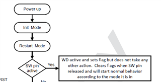
My customer is trying to enter no watchdog mode via SW pin configuration, please help assist in confirming the correct configuration method.

Refer to the circuit above, customer connected I421 and I407, the RESET pin is periodically be pulled down and remains 1S+ after powering up, so the customer suspects that it may not have successfully entered no watchdog mode. 

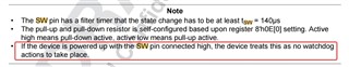
1. May I know if the current SW pin configuration meets the requirement to enter no watchdog mode?

2. Are specific power-up timing or other pin state mates required?

3. Are there other common reasons why Watchdog is not disabled?

Thank you!

Regards,

Ivy

  • Hi Ivy,

    Parker is our expert on this device, and he is out of office today. He will return tomorrow.

    Thanks for your patience,

    -Ethan

  • Hi Ivy,

    I apologize for the delay here! 

    So first - there is a bit of a misunderstanding - holding the SW pin in its active state (default) high doesn't shut off the watchdog - it just disables the SBC from taking action due to a missed watchdog - if you truly want to turn it off - you need to turn it off in the configuration registers. The difference is that watchdog is still on with SW pulled high - so the current consumption from watchdog is still there - however, from a behavioral point of view the device with SW pulled to active state  is going to operate very similarly to a device that has truly disabled watchdog. 

    For your direct questions:

    1. So to be clear they have a 10k R25 connected to SW and 3.3V - have they confirmed that the SW pin is seeing 3.3V? I am assuming the 3.3V is coming from VCC1 - as that is generally what we'd suggest if included

    2. No - not really. If connected to VCC1 SW will be pulled high when VCC1 is active which is enough to disable action due to missed watchdog. However that assumes that the SW pin is kept as active high  - if you can have customer check register address Eh bit 0 - it should be 0b1 if the SW pin is active high - if it is 0b0 then the SW pin is active low. it should default to active high - but just double check to make sure there wasn't a trimming issue. Here is the specific flow - if you have the datasheet the full diagram is on page 86. 

    You can see that as soon as the device transitions out of restart mode it checks the state of the SW pin - if active WD isn't disabled but the actions are. 

    3. If bit 0 equals 0b1 in register Eh and VCC1 is connected to SW watchdog action should be disabled - I have never seen an issue with this pins function - so I would just double check to make sure the SW pin voltage is correct and that the bit in the registers are correct. If you are having trouble checking the register due to the watchdog timer and the voltage on SW is high - try removing R425 and placing R19 (it looks to be DNP'd) - to force SW low - if the device doesn't reset after then the SW pin has be configured active low for some reason. 

    Please let me know if you have performed all these checks and report back to me if any of them worked ; also I would double check on a second part if you have only tested one (if you have another part) - just to see if there could be a bad part for some reason. 

    Best,

    Parker Dodson