This thread has been locked.

If you have a related question, please click the "Ask a related question" button in the top right corner. The newly created question will be automatically linked to this question.

TL16C754C: External clock frequency supported by TL16C754C IC

Part Number: TL16C754C

Tool/software:

Hi Team,

We are using the quad UART IC (TL16CP754CIPMR).

We wanted to know if an external clock of 7.327 MHz frequency will be supported on this IC. If so, can we get a list of the divisor values, to get 16x of the clock. Is there a margin of error that is acceptable if we were to use this clock?

  • This device supports all external clock frequencies between 0 Hz and at least 16 MHz.

    divisor = clock / 16 / baud_rate

    The error must be smaller than 2.5 %.

  • Clemens is correct. The rule of thumb with baud rate mismatches is a total of 5%. So if both UART terminals can only have a difference of 5% when added together then each one individually should be no more than +/-2.5% mismatched from each other.

    -Bobby

  • Hi Bobby,

    Thanks for your support.

    1) We previously had a uart that had rx fifo trigger level at 8 characters, we do not have such an option with this IC, is there a way we can replicate this trigger level using any of the registers?

    2) The datasheet mentions that we can use any clock upto 24mhz, but the datasheet has example baud rates only for 1.8432-MHz and 3.072-MHz, does that mean any value greater than 3.072 mhz has to be prescaled for accurate baud rate generation ?

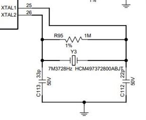
    3) We have used an external crystal having 7.3278 mhz having the following circuitry. Since no example circuitry has been provided for this clock, can you confirm if we have made all the necessary calculation wrt the resistors and capacitors.

    4) what is the highest baud rate supported by the device, especially when we are using the 7.327 mhz clock 


    Thank you,

    Gokul

  • 1) We previously had a uart that had rx fifo trigger level at 8 characters, we do not have such an option with this IC, is there a way we can replicate this trigger level using any of the registers?

    You should be able to set the trigger level for RX to 8 by writing to the TLR[7:4]. 0b0010 XXXX

    2) The datasheet mentions that we can use any clock upto 24mhz, but the datasheet has example baud rates only for 1.8432-MHz and 3.072-MHz, does that mean any value greater than 3.072 mhz has to be prescaled for accurate baud rate generation ?

    The baud rate examples are just copy pasted from another datasheet. You can use up to 48MHz if you are planning to use a crystal but it depends on your Vcc level. Page 22 in the datasheet showcases the max crystal it can support. 

    3) We have used an external crystal having 7.3278 mhz having the following circuitry. Since no example circuitry has been provided for this clock, can you confirm if we have made all the necessary calculation wrt the resistors and capacitors.

    I think it may depend on the crystal you choose. I'm not aware of the formula/equation required to calculate this but the components you included can be modified later when the PCB is assembled and you probe the two XTAL pins to look for stable oscillation.

    4) what is the highest baud rate supported by the device, especially when we are using the 7.327 mhz clock 

    This is the equation to calculate the divisor. The smallest value the divisor can technically be is 0. 

    Divisor = (XTAL crystal input frequency / prescaler) / (desired baud rate 16)

    Assuming prescaler is 1 and the divisor is 1, then it would be about 457987. If you used 0 divisor then you can multiply the previous answer by 2 or 915975. 

    -Bobby

  • Hi Bobby,

    Thanks for your support.

    I have configured for the RX trigger level from 4byte to 8 byte. So, uart1,uart2 and uart3 are working fine. But uart 0 (device[0]) is not working. 

    Following are the snippet of our configuration.

    #define ADI_UART_LCR_DEFAULT ((u16)0x0000)      // default LCR value
    #define ADI_UART_FCR_DEFAULT ((u16)0x004F)      // default FCR value
    #define ADI_UART_MCR_DEFAULT ((u16)0x0008)      // default MCR value
    #define ADI_UART_IER_DEFAULT ((u16)0x0000)      // default IER value
    #define ADI_UART_DLL_DEFAULT ((u16)0x0001)      // default DLL value
    #define ADI_UART_DLH_DEFAULT ((u16)0x0000)      // default DLH value
                       
    for (i = 0; i < ADI_UART_NUM_DEVICES; i++) {
                        pDevice          = &Device[i];
                   
                        ADI_UART_LCR_SET(ADI_UART_LCR_DEFAULT);
                        ADI_UART_MCR_SET(0x0);
                        ADI_UART_IER_SET(ADI_UART_IER_DEFAULT);
                        
                        //ADI_UART_FCR_SET(0x01);
                        //ADI_UART_FCR_SET(ADI_UART_FCR_DEFAULT);
                   
                        // TLR 8 CHARACTER INTERRUPT CONFIGURATION
                   
                        ADI_UART_LCR_SET(0xBF);
                        ADI_UART_EFR_SET(0x10);
                        ADI_UART_LCR_SET(ADI_UART_LCR_DEFAULT);
                        ADI_UART_MCR_SET(0x40);  
                        ADI_UART_TLR_SET(0x20);
                        ADI_UART_EFR_SET(0x0);
                   
                        ADI_UART_LCR_SET_DLAB();
                        ADI_UART_DLL_SET(ADI_UART_DLL_DEFAULT);
                        ADI_UART_DLH_SET(ADI_UART_DLH_DEFAULT);
                        ADI_UART_LCR_CLEAR_DLAB();
                        do {
                            isr = ADI_UART_ISR_GET();
                            rbr = ADI_UART_RBR_GET();
                            lsr = ADI_UART_LSR_GET();
                        } while ((isr & 0x01) != 0x01);  
    }
    Could you please check and suggest us if we need to consider any configuration changes.
    Kindly let us know for further inputs.
    Thanks & Regards,
    Gokul S
  • Hi Gokul,

    Do you have a schematic I could quickly double check?

    But uart 0 (device[0]) is not working. 

    What exactly is not working? Are you seeing the baud rate is incorrect? Or it's the Rx trigger level?

    -Bobby