This thread has been locked.

If you have a related question, please click the "Ask a related question" button in the top right corner. The newly created question will be automatically linked to this question.

TCAN4550: TCAN4550/Microchip PIC32 not sending FD packets

Part Number: TCAN4550

Tool/software:

My name is Sid G, I work for a company named Arboreal Systems and we design and produce Power Distribution products that are controlled using Bluetooth LE. They are used on vehicles such as motor cycles, boats, jeeps etc. I developed a product 5 years ago called Apogee which uses the TCAN4550 to communicate with other Apogees using CAN FD Bus. This was a working/shipping product till Covid hit and so we had a slow down at that point. The Apogee is once again in demand and we found that we're having problems getting CAN  FD up and running again. The Apogee uses a Processor from Microchip, the PIC32MZ2048EFH and the only thing that changed during the slowdown was the microchip compiler. The code compiles with no errors and every thing works on the Apogee including sending classic can messages through the TCAN but when I try to send an FD message through the TCAN the CAN bus locks up because the FD message is not seeing an ACK and starts repeating forever. I have two Apogees on the bus in this setup. I don't think this is a bus problem as such. Suspect this to be a setting on the TCAN that is incorrect so the question is what setting is incorrect that allows ACK to work for Classic Can packets that would prevent ACK from being generated for FD packets?

  • Hello Sid G,

    This is an interesting question.  The only way a device can start repeating transmission forever is when there is a silent bus and no other devices on the bus are in a functional state.  If a CAN FD message is transmitted on a bus that does not support CAN FD, then the non-FD nodes will see the CAN FD as containing an error and transmit an Error Frame on the CAN FD message.  Eventually the CAN FD transmitting node's transmit error counter will exceed the max limit and the node will enter a Bus Off condition and remove itself from participating in bus communication.  If you only have two nodes on the bus, and one of them enters a Bus Off condition, then the other node will be transmitting into a silent bus and allow for it to repeatedly try to transmit a message but will never receive an acknowledgement or error frame.

    Verify that the FD Operation Enable (FDOE) and also the Bit Rate Switch Enable (BRSE) bits in the Control Register 0x1018[9:8] are both set to "1" (assuming you are also using bit rate switching on your FD messages).

    Then also verify the Nominal and Data Bit Timing register values are the same and match your CAN FD message bit rate settings in registers 0x101C and 0x100C.  If these are different, then the devices will not correctly sample the bits and generate errors.

    I don't know how many data bytes you are using in your FD messages, but make sure the TX buffer elements have enough space to hold the full data message length.  The Tx Buffer Element Size Configuration register determines how many data bytes are allocated in memory for a TX Buffer element.  This should be set large enough to hold your largest message, or just set to the max 64-byte size if you are unsure.  If you don't allocate enough space then your processor will overwrite some other elements that could cause errors.

    Verify your TX messages buffer elements have correctly set the FD Format (FDF) and Bit Rate Switch (BRS) bits as well as the correct Data length Code (DLC) for your FD message.

    Assuming your devices have the same configuration settings and the TX message bits are formatted correctly, then the two devices should be able to communicate with either Classic CAN or CAN FD messages. 

    If possible try to read and log the device Interrupt, status, and error counter registers to determine the state of the device so that you can work out the sequence of events leading up to your current situation (0x0820, 0x0824 or 0x1050, 0x1018, 0x1040, 0x1044).

    You could also monitor the TX message transmission by reading the TX FIFO/Queue Status, Request Pending, and Transmission Occurred registers (0x10C4, 0x10CC, 0x10D8).

    I suspect that you will find the node that is repeatedly attempting to transmit the message will have the corresponding bit in the TX Buffer Request Pending register set to 1, and the other node will have entered a Bus Off condition and set the INIT bit in the Control Register 0x1018[0] = 1.

    In addition to the datasheet, I would recommend these other two guides for additional information.

    TCAN45xx Software User's Guide (Link)

    M_CAN User's Manual (Link)

    Regards,

    Jonathan

  • Jonathan,

    Thanks for responding to my message. I have simplified my test setup a bit. Using one Apogee as the CAN message receiver and a Peak systems USB CAN FD transmitter I can send a classic message to the Apogee with no problem but if I send that same message to the same address with the FD bit set regardless of the Bit Rate setting it will fail. I have a scope hooked up to the bus capture the signal and I do see an ACK happening to the first frame. The Ack measures 12us wide but no interrupt is generated and the message begins to repeat as it should before the bus shuts down. I'm including my canfd_init.c code which verifies the setting and I do a SYS_DEBUG_Print of the filter settings as well and all looks good. Again this was working code.

    Sid

    /* ************************************************************************** */
    /** Descriptive File Name

    @Company
    Company Name

    @File Name
    filename.c

    @Summary
    Brief description of the file.

    @Description
    Describe the purpose of this file.
    */
    /* ************************************************************************** */

    /* ************************************************************************** */
    /* ************************************************************************** */
    /* Section: Included Files */
    /* ************************************************************************** */
    /* ************************************************************************** */

    #include "system_config.h"
    #include "system_definitions.h"
    #include "../Apogee.X/TCAN4x5x_Reg.h"
    #include "../Apogee.X/TCAN4x5x_Data_Structs.h"
    #include "../Apogee.X/TCAN4550.h"
    #include "app.h"
    #include "global_var.h"

    /* ************************************************************************** */
    /* ************************************************************************** */
    /* Section: File Scope or Global Data */
    /* ************************************************************************** */
    /* ************************************************************************** */

    /* A brief description of a section can be given directly below the section
    banner.
    */

    /* ************************************************************************** */
    /** Descriptive Data Item Name

    @Summary
    Brief one-line summary of the data item.

    @Description
    Full description, explaining the purpose and usage of data item.
    <p>
    Additional description in consecutive paragraphs separated by HTML 
    paragraph breaks, as necessary.
    <p>
    Type "JavaDoc" in the "How Do I?" IDE toolbar for more information on tags.

    @Remarks
    Any additional remarks
    */

    /* ************************************************************************** */
    /* ************************************************************************** */
    // Section: Local Functions */
    /* ************************************************************************** */
    /* ************************************************************************** */

    void Init_CAN_FD(void) {
    TCAN4x5x_Device_ClearSPIERR(); // Clear any SPI ERR flags that might be set as a result of our pin mux changing during MCU startup

    /* Step one attempt to clear all interrupts */
    TCAN4x5x_Device_Interrupt_Enable dev_ie = {{0}}; // Initialize to 0 to all bits are set to 0.
    TCAN4x5x_Device_ConfigureInterruptEnable(&dev_ie); // Disable all non-MCAN related interrupts for simplicity

    TCAN4x5x_Device_Interrupts dev_ir = {{0}}; // Setup a new MCAN IR object for easy interrupt checking
    TCAN4x5x_Device_ReadInterrupts(&dev_ir); // Request that the struct be updated with current DEVICE (not MCAN) interrupt values

    if (dev_ir.PWRON) // If the Power On interrupt flag is set
    TCAN4x5x_Device_ClearInterrupts(&dev_ir); // Clear it because if it's not cleared within ~4 minutes, it goes to sleep

    /* Configure the CAN bus speeds */
    TCAN4x5x_MCAN_Nominal_Timing_Simple TCANNomTiming = {0,0,0}; // 500k arbitration with a 40 MHz crystal ((40E6 / 2) / (32 + 8) = 500E3)
    TCANNomTiming.NominalBitRatePrescaler = 2;
    TCANNomTiming.NominalTqBeforeSamplePoint = 32;
    TCANNomTiming.NominalTqAfterSamplePoint = 8;

    TCAN4x5x_MCAN_Data_Timing_Simple TCANDataTiming = {0,0,0}; // 2 Mbps CAN FD with a 40 MHz crystal (40E6 / (15 + 5) = 2E6)
    TCANDataTiming.DataBitRatePrescaler = 1;
    TCANDataTiming.DataTqBeforeSamplePoint = 15;
    TCANDataTiming.DataTqAfterSamplePoint = 5;

    /* Configure the MCAN core settings */
    TCAN4x5x_MCAN_CCCR_Config cccrConfig = {{0}}; // Remember to initialize to 0, or you'll get random garbage!
    cccrConfig.FDOE = 1; // CAN FD mode enable
    cccrConfig.BRSE = 1; // CAN FD Bit rate switch enable

    TCAN4x5x_MCAN_Global_Filter_Configuration gfc = {{0}};
    gfc.RRFE = 0; // Reject remote frames (TCAN4x5x doesn't support this)
    gfc.RRFS = 0; // Reject remote frames (TCAN4x5x doesn't support this)
    gfc.ANFE = TCAN4x5x_GFC_REJECT;
    gfc.ANFS = TCAN4x5x_GFC_REJECT;

    /* ************************************************************************
    * In the next configuration block, we will set the MCAN core up to have:
    * - 2 SID filter element
    * - 1 XID Filter element
    * - 5 RX FIFO 0 elements
    * - RX FIFO 0 supports data payloads up to 64 bytes
    * - 2 RX FIFO 1 elements
    * - RX FIFO 1 supports data payloads up to 64 bytes
    * - RX Buffer will not have any elements, but we still set their data payload sizes, even though it's not required
    * - No TX Event FIFOs
    * - 2 Transmit buffers supporting up to 64 bytes of data payload
    */
    TCAN4x5x_MRAM_Config MRAMConfiguration = {0};
    MRAMConfiguration.SIDNumElements = 2; // Standard ID number of elements, you MUST have a filter written to MRAM for each element defined
    MRAMConfiguration.XIDNumElements = 1; // Extended ID number of elements, you MUST have a filter written to MRAM for each element defined
    MRAMConfiguration.Rx0NumElements = 5; // RX0 Number of FIFO elements
    MRAMConfiguration.Rx0ElementSize = MRAM_64_Byte_Data; // RX0 data payload size
    MRAMConfiguration.Rx1NumElements = 2; // RX1 number of elements
    MRAMConfiguration.Rx1ElementSize = MRAM_64_Byte_Data; // RX1 data payload size
    MRAMConfiguration.RxBufNumElements = 0; // RX buffer number of elements
    MRAMConfiguration.RxBufElementSize = MRAM_64_Byte_Data; // RX buffer data payload size
    MRAMConfiguration.TxEventFIFONumElements = 0; // TX Event FIFO number of elements
    MRAMConfiguration.TxBufferNumElements = 2; // TX buffer number of elements
    MRAMConfiguration.TxBufferElementSize = MRAM_64_Byte_Data; // TX buffer data payload size


    /* Configure the MCAN core with the settings above, the changes in this block are write protected registers, *
    * so it makes the most sense to do them all at once, so we only unlock and lock once */

    if (!TCAN4x5x_MCAN_EnableProtectedRegisters()) { // Start by making protected registers accessible
    SetStatLED(Red);
    SYS_DEBUG_Print("\r\nTCAN4x5x_MCAN_EnableProtectedRegisters Failed");
    }
    if (!TCAN4x5x_MCAN_ConfigureCCCRRegister(&cccrConfig)) { // Enable FD mode and Bit rate switching
    SetStatLED(Red);
    SYS_DEBUG_Print("\r\nCCCRReg Programming failed, TCAN4x5x_MCAN_ConfigureCCCRRegister");
    }
    if (!TCAN4x5x_MCAN_ConfigureGlobalFilter(&gfc)) { // Configure the global filter configuration (Default CAN message behavior)
    SetStatLED(Red);
    SYS_DEBUG_Print(",\r\nTCAN4x5x_MCAN_ConfigureCCCRRegister");
    }
    if (!TCAN4x5x_MCAN_ConfigureNominalTiming_Simple(&TCANNomTiming)) { // Setup nominal/arbitration bit timing
    SetStatLED(Red);
    SYS_DEBUG_Print(",\r\nTCAN4x5x_MCAN_ConfigureNominalTiming_Simple");
    }
    if (!TCAN4x5x_MCAN_ConfigureDataTiming_Simple(&TCANDataTiming)) { // Setup CAN FD timing
    SetStatLED(Red);
    SYS_DEBUG_Print(",\r\nTCAN4x5x_MCAN_ConfigureDataTiming_Simple");
    }
    TCAN4x5x_MRAM_Clear(); // Clear all of MRAM (Writes 0's to all of it)
    if (!TCAN4x5x_MRAM_Configure(&MRAMConfiguration)) { // Set up the applicable registers related to MRAM configuration
    SetStatLED(Red);
    SYS_DEBUG_Print(",\r\nTCAN4x5x_MRAM_Configure");
    }
    if (!TCAN4x5x_MCAN_DisableProtectedRegisters()) { // Disable protected write and take device out of INIT mode
    SetStatLED(Red);
    SYS_DEBUG_Print("\r\nTCAN4x5x_MCAN_DisableProtectedRegisters Failed"); 
    }


    /* Set the interrupts we want to enable for MCAN */
    TCAN4x5x_MCAN_Interrupt_Enable mcan_ie = {{0}}; // Remember to initialize to 0, or you'll get random garbage!
    mcan_ie.RF0NE = 1; // RX FIFO 0 new message interrupt enable
    mcan_ie.RF0WE = 1; // RX FIFO 0 watermark interrupt enable 
    mcan_ie.RF0FE = 1; // RX FIFO 0 full interrupt enable
    mcan_ie.RF1NE = 1; // RX FIFO 1 new message interrupt enable
    mcan_ie.RF1FE = 1; // RX FIFO 1 full interrupt enable

    TCAN4x5x_MCAN_ConfigureInterruptEnable(&mcan_ie); // Enable the appropriate registers


    /* Setup filters, this filter will mark any message with ID 0x120 - 0x127 */
    TCAN4x5x_MCAN_SID_Filter SID_ID = {{0}};
    SID_ID.SFT = TCAN4x5x_SID_SFT_CLASSIC; // SFT: Standard filter type. Configured as a classic filter
    SID_ID.SFEC = TCAN4x5x_SID_SFEC_STORERX0; // Standard filter element configuration, store it in RX fifo 0 as a priority message
    SID_ID.SFID1 = CanFD_AddrSid[CAN_FD_INDEX]; // The current master/slave index 0 = master 1 - 7 = slave
    if (CAN_FD_INDEX == Master) { // Is it For a master or slave
    SID_ID.SFID2 = 0x7F8; // SFID2 Master accepts all 8 addresses 0x0120 - 0x127
    } else { // Must be a slave
    SID_ID.SFID2 = 0x7FF; // SFID2 Full mask only accept the programmed address 
    }
    SYS_DEBUG_Print("\r\nCAN_FD_INDEX: %d CanID: 0x%03X Filter: 0x%03X",CAN_FD_INDEX,SID_ID.SFID1,SID_ID.SFID2);
    if (!TCAN4x5x_MCAN_WriteSIDFilter(0, &SID_ID)) { // Write to the MRAM
    SetStatLED(Red);
    SYS_DEBUG_Print("\r\nTCAN4x5x_MCAN_WriteSIDFilter Failed");
    } // Set this filter ID of 0x50 only
    SID_ID.SFT = TCAN4x5x_SID_SFT_CLASSIC; // SFT: Standard filter type. Configured as a classic filter
    SID_ID.SFEC = TCAN4x5x_SID_SFEC_PRIORITYSTORERX0; // Standard filter element configuration, store it in RX fifo 0 as a priority message
    SID_ID.SFID1 = 0x050; // SFID1 (Classic mode Filter) address 0x050
    SID_ID.SFID2 = 0x7FF; // SFID2 (Classic mode Mask)
    SYS_DEBUG_Print("\r\nCAN_FD_INDEX: %d CanID: 0x%03X Filter: 0x%03X",CAN_FD_INDEX,SID_ID.SFID1,SID_ID.SFID2);
    if (!TCAN4x5x_MCAN_WriteSIDFilter(1, &SID_ID)) { // Write to the MRAM
    SetStatLED(Red);
    SYS_DEBUG_Print("\r\nTCAN4x5x_MCAN_WriteSIDFilter Failed");
    }

    /* Store ID 0x12345678 as a priority message */
    TCAN4x5x_MCAN_XID_Filter XID_ID = {0};
    XID_ID.EFT = TCAN4x5x_XID_EFT_CLASSIC; // EFT
    XID_ID.EFEC = TCAN4x5x_XID_EFEC_PRIORITYSTORERX0; // EFEC
    XID_ID.EFID1 = 0x12345678; // EFID1 (Classic mode filter) address 0x12345678
    XID_ID.EFID2 = 0x1FFFFFFF; // EFID2 (Classic mode mask)
    SYS_DEBUG_Print("\r\nCAN_FD_INDEX: %d CanXID: 0x%03X XFilter: 0x%03X",CAN_FD_INDEX,XID_ID.EFID1,XID_ID.EFID2);
    if (!TCAN4x5x_MCAN_WriteXIDFilter(0, &XID_ID)) { // Write to the MRAM
    SetStatLED(Red);
    SYS_DEBUG_Print("\r\nTCAN4x5x_MCAN_WriteXIDFilter Failed");
    } // Write to the MRAM

    /* Configure the TCAN4550 Non-CAN-related functions */
    TCAN4x5x_DEV_CONFIG devConfig = {{0}}; // Remember to initialize to 0, or you'll get random garbage!
    devConfig.SWE_DIS = 0; // Keep Sleep Wake Error Enabled (it's a disable bit, not an enable)
    devConfig.DEVICE_RESET = 0; // Not requesting a software reset
    devConfig.WD_EN = 0; // Watchdog disabled
    devConfig.nWKRQ_CONFIG = 0; // Mirror INH function (default)
    devConfig.INH_DIS = 1; // INH disabled
    devConfig.GPIO1_GPO_CONFIG = TCAN4x5x_DEV_CONFIG_GPO1_MCAN_INT1; // MCAN nINT 1 (default)
    devConfig.FAIL_SAFE_EN = 0; // Failsafe disabled (default)
    devConfig.GPIO1_CONFIG = TCAN4x5x_DEV_CONFIG_GPIO1_CONFIG_GPO; // GPIO set as GPO (Default)
    devConfig.WD_ACTION = TCAN4x5x_DEV_CONFIG_WDT_ACTION_nINT; // Watchdog set an interrupt (default)
    devConfig.WD_BIT_RESET = 0; // Don't reset the watchdog
    devConfig.nWKRQ_VOLTAGE = 0; // Set nWKRQ to internal voltage rail (default)
    devConfig.GPO2_CONFIG = TCAN4x5x_DEV_CONFIG_GPO2_NO_ACTION; // GPO2 has no behavior (default)
    devConfig.CLK_REF = 1; // Input crystal is a 40 MHz crystal (default)
    devConfig.WAKE_CONFIG = TCAN4x5x_DEV_CONFIG_WAKE_DISABLED; // Wake pin disabled
    if (!TCAN4x5x_Device_Configure(&devConfig)) { // Configure the device with the above configuration
    SetStatLED(Red);
    SYS_DEBUG_Print("\r\nTCAN4x5x_Device_Configure Failed");
    }

    if (!TCAN4x5x_Device_SetMode(TCAN4x5x_DEVICE_MODE_NORMAL)) { // Set to normal mode, since configuration is done. This line turns on the transceiver
    SetStatLED(Red);
    SYS_DEBUG_Print("\r\nTCAN4x5x_Device_SetMode Failed");
    }
    TCAN4x5x_MCAN_ClearInterruptsAll(); // Resets all MCAN interrupts (does NOT include any SPIERR interrupts)
    appData.CANFDState = CANFD_STATE_SPING_CHECK; // Send out a slave ready ping if not master
    }

    /* *****************************************************************************
    End of File
    */

  • Hi Sid,

    Thanks for providing your configuration code, I didn't see anything obvious to explain why a FD message wouldn't work when a Classic message does.

    You did say something that caught my attention:

    I have a scope hooked up to the bus capture the signal and I do see an ACK happening to the first frame. The Ack measures 12us wide but no interrupt is generated and the message begins to repeat as it should before the bus shuts down.

    From the code it appears the Nominal Bit Time is setup for 500kbps.  If that's correct, then a single nominal bit period is 2us.  

    The ACK timeslot is only 2 bit times wide, which has one bit time for the ACK bit and the second bit time as an ACK delimiter which is always recessive.  This allows for the ACK bits to be received from other devices on the far end of the bus to be received which may arrive during the delimiter pulse.

    So, at most, an ACK bit should be no longer than 4us when using 500kbps.  However, with your simple setup, you should just see a single additional 2us ACK bit at the end of the message.

    What I believe you are seeing instead of an "ACK" is an "Error Frame" which is 6 bit times followed by an 8 recessive bit delimiter.  The CAN protocol defines the maximum number of consecutive 1's or 0's transmitted on the bus to be 5.  If normal data requires more than 5 consecutive 1's or 0's the controller will add a "stuff bit" of opposite polarity to message, and the receiving nodes will automatically remove these stuff bits per the protocol. 

    Therefore 6 consecutive dominant bits will be seen as an error and is why it is used intentionally as an error frame.  Your measurement of 12us coincidentally matches a 6 bit error frame (6 bits * 2us = 12us).

    When an error frame is thrown on a message, the message is discarded by all receiving nodes and the various Transmit and Receive Error Counters are incremented.  This is likely why you do not receive a new message interrupt, and eventually the nodes enter a bus off condition based on the error counters.

    The most common reasons for errors are incompatible bit time configurations causing sampling errors.  Sometimes when using Bit Rate Switching, the actual sample point % can cause an issue if they are different.  This is because the switch the faster bit rate occurs a the sample point of the BRS bit in the message and nodes with different sample points can see the rate switch as a bit error.  This is a general comment though.

    Can you verity the Nominal and Data bit widths on the scope match the bit times you are programming?  Also make sure your PCAN-USB has the same settings.

    I know you are having an issue receiving a CAN FD message, but do you also have an issue transmitting a CAN or CAN FD message from the TCAN4550 to the PCAN-USB?

    Is it possible to read the Protocol Status Register and Error Counter Registers (0x1040 and 0x1044) after message transmission or reception to get additional information on the type of error that was detected and what error counter was adjusted?

    Regards,

    Jonathan

  • Jonathan,

       I had to take a two week timeout with a cabin full of family members over the fourth of July. Now I'm back at it trying to decode what's going on with FD. I created a command that I can send over the FD bus in classic mode that will allow the protocol status reg (PSR) and error counter reg (ECR) to print out. I first convert the classic message to an FD message by setting the can FD bit only, send the message which causes the bus error; reset the bus and convert the message back to classic and send the message again and read the PSR reg = 0x0000708, ECR reg = 0x00201F00. Convert the message back to FD this time setting the FD bit and the bit rate switch then send out the message on the FD bus which locks up. Restore the message to classic and send out, this time the PSR = 0x00000248 and the ECR = 0x00197E00.

       Sid

  • Hi Sid,

    I hope you enjoyed your family vacation and the 4th of July Holiday!

    PSR reg = 0x0000708, ECR reg = 0x00201F00

    LEC= 3'b000 --> No Error occurred since LEC has been reset by successful reception or transmission

    DLEC = 3'b111 --> No Change since last register read.  (should be cleared to 3'b000 when a CAN FD format frame with its BRS flag set has been transferred (reception or transmission) without error.)

    This field will be cleared to zero when a CAN FD format frame with
    its BRS flag set has been transferred (reception or transmission) without error.

    REC= 31

    CEL = 16

    PSR = 0x00000248 and the ECR = 0x00197E00

    LEC= 3'b000 --> No Error occurred since LEC has been reset by successful reception or transmission

    DLEC = 3'b010 -->Form Error: A fixed format part of a received frame has the wrong format.

    EW = 1 --> At least one of the error counters has reached the Error_Warning limit of 96

    REC= 126

    CEL = 25

    So you are definitely errors receiving frames, and the PSR register indicated a Form Error which means that there was a sampling error during a bit that is of fixed value.

    The following components of a CAN frame are considered static fields, since their data level is always recessive.

    • CRC Delimiter
    • ACK Delimiter
    • End of Frame Field
    • Intermission Field

    These components are used to check the consistency of the frame and a Form Error is detected with any of these components contain a dominant bit.

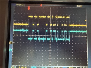
    Clock Tolerance and or different bit timing configurations can often result in these types of errors, but there could be other factors.  You previously mentioned that you had a scope connected, so are you able to share the scope plots for the CAN messages and error frames?  The receiving node should immediately throw an error frame on the bus when it detects an error, so the location of the 6-bit error frame may allow us to determine which of these static bit fields caused the error.

    You also mentioned you were using PCAN-USB interface, and I also have this tool.  Can you share the PCAN bit timing configuration settings for this tool? 

    Can you also share what the specific CAN/CAN FD message you are using as a test message that is causing the error when transmitted as FD?  I could try to replicate and check for errors.

    If possible, I could also load in the same TCAN4550 register configuration if you can do a read-back of every register and provide that as a simple list.  This would allow me to have the same configuration for PCAN and TCAN4550 that you have.

    Regards,

    Jonathan

  • Jonathan,

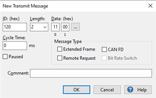
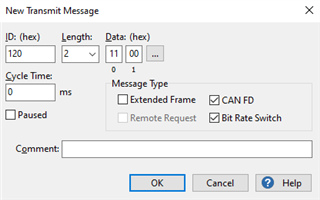
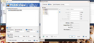
       Both the PCAN and the TCAN4550 are set at Nominal 500K Bit/s, Data 2M Bits/s. The TCAN init file is above sent earlier, it came with IT's development package. The data I send out of the PCAN to address 0x120 is two bytes 0x1100, it is a command to the Apogee to print out the PSR and PCR. I added to the command to send out a FD message and when that happens the BUS locks up as it does sending out an FD message from the PCAN. I'm going to download a photo of a that message repeating from the scope, hope tis good enough to see.

  • Hi Sid,

    I'm sorry if I wasn't clear. What I was trying to ask for was the actual bit timing configuration for your PCAN including the Clock Frequency (20MHz, 40MHz, or 80MHz), Sample Point %, TSEG1, TSEG2, Prescaler, Sync Jump Width settings, etc. that create the bit rate of 500K / 2M bit rates.

    CAN FD applications are more sensitive to the bit timing configuration and sample point due to the faster bit rates and sample point locations.  It is recommended that all CAN FD nodes have the same bit timing configuration to ensure the bits are sampled at the same bit location and that the bit rate switch occurs in all nodes at the same time if BRS is used.  The bit rate switch occurs at the sample point of the BRS bit in the message, and if there are different sample point configurations, or the number of tq is different (due to a different clock frequency or prescaler), then sampling and bit errors can occur.

    Because both the TCAN4550 and PCAN are "theoretically" configured to accept both Classic CAN and CAN FD messages, We need to rule out the bit timing configuration as the reason for the bit errors in the message transmission, and this requires a more detailed evaluation of the settings beside the high level 500k/2M description.

    The TCAN init file you provide contains this information for the TCAN4550, but can you verify the PCAN is configured with the same values?

    /* Configure the CAN bus speeds */
    TCAN4x5x_MCAN_Nominal_Timing_Simple TCANNomTiming = {0,0,0}; // 500k arbitration with a 40 MHz crystal ((40E6 / 2) / (32 + 8) = 500E3)
    TCANNomTiming.NominalBitRatePrescaler = 2;
    TCANNomTiming.NominalTqBeforeSamplePoint = 32;
    TCANNomTiming.NominalTqAfterSamplePoint = 8;

    TCAN4x5x_MCAN_Data_Timing_Simple TCANDataTiming = {0,0,0}; // 2 Mbps CAN FD with a 40 MHz crystal (40E6 / (15 + 5) = 2E6)
    TCANDataTiming.DataBitRatePrescaler = 1;
    TCANDataTiming.DataTqBeforeSamplePoint = 15;
    TCANDataTiming.DataTqAfterSamplePoint = 5;

    If you are using the provided PCAN-View the setup allows you to customize the configuration. 

    If you press the Copy Parameters to Clipboard button, you will get a string of the timing parameters like the following.  This string is also used in the other interface methods for the PCAN USB tools such as with the SDK, etc.

    f_clock=40000000,nom_brp=2,nom_tseg1=31,nom_tseg2=8,nom_sjw=8,data_brp=1,data_tseg1=15,data_tseg2=4,data_sjw=1

    For the transmitted message, do I understand you correctly with the following message information?

    Classic Message Format

    CAN FD with BRS Message Format:

    Another possible cause for bit timing is a crystal oscillation frequency that is out of spec.  The crystal frequency is directly used to create the Time Quanta (Tq) that make up the CAN bit periods.  Therefore if the crystal is oscillating at an incorrect frequency the the CAN bit periods will out of spec as well and this could lead to sampling errors as well.  It may be worth verifying the crystal oscillation frequency is correct and nothing changed over the years with the crystal or load capacitance in this new build.

    Regards,

    Jonathan

  • Jonathan,

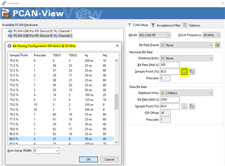
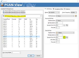
       Here are my screenshots of the Peak timing setup, different from what you show.

    Sid

  • Yes your Pcan settings match mine but sometimes I don't set the bit rate switch with the same failure.

  • Hi Sid,

    Thanks for the information.  I think I have been able to reproduce your error, or at least one of them if more than one exists.  I believe the issue is with the Nominal Bit Timing parameters not being the same between your PCAN and the TCAN4550.  They have sample point % which is causing an error when you try to transmit a FD message with BRS. 

    Notice the time quanta allocation for the TCAN4550 gives 40 tq per bit, and the distribution yields an 80% sample point.  However, in your PCAN tool, you are only using 16 tq per bit and the distribution yields a 75% sample point.

    I believe the

    /* Configure the CAN bus speeds */
    TCAN4x5x_MCAN_Nominal_Timing_Simple TCANNomTiming = {0,0,0}; // 500k arbitration with a 40 MHz crystal ((40E6 / 2) / (32 + 8) = 500E3)
    TCANNomTiming.NominalBitRatePrescaler = 2;
    TCANNomTiming.NominalTqBeforeSamplePoint = 32;
    TCANNomTiming.NominalTqAfterSamplePoint = 8;

    TCAN4x5x_MCAN_Data_Timing_Simple TCANDataTiming = {0,0,0}; // 2 Mbps CAN FD with a 40 MHz crystal (40E6 / (15 + 5) = 2E6)
    TCANDataTiming.DataBitRatePrescaler = 1;
    TCANDataTiming.DataTqBeforeSamplePoint = 15;
    TCANDataTiming.DataTqAfterSamplePoint = 5;

    When I configure my PCAN tool to have the exact same Nominal tq configuration as the TCAN4550, I do not have any errors transmitting the message in Classic CAN, CAN FD w/o BRS or CAN FD w/ BRS.

    However, when I change the Nominal tq configuration to match yours with the 75% sample point, I get an error transmitting the message in CAN FD w/BRS format.  But I don't have any errors transmitting the message in a Classical CAN or in a CAN FD w/o BRS. 

    This tells me that the error is limited to the BRS and it has to do with the sample point mismatch.

    As I previously mentioned, the switch to the faster FD bit rate occurs at the Sample Point location of the BRS bit in the message.  If the nodes on the bus have different sample points, then they will transition to the FD bit rate at different times and this can lead to one or more nodes incorrectly sampling the BRS and data bits because some nodes have switched to the FD rate, and others are still on the Nominal rate.

    CAN FD applications are more sensitive to the bit timing configuration and sample point due to the faster bit rates and sample point locations.  It is recommended that all CAN FD nodes have the same bit timing configuration to ensure the bits are sampled at the same bit location and that the bit rate switch occurs in all nodes at the same time if BRS is used.  The bit rate switch occurs at the sample point of the BRS bit in the message, and if there are different sample point configurations, or the number of tq is different (due to a different clock frequency or prescaler), then sampling and bit errors can occur.

    The Data bit timing is not as critical with the tq because only one device is transmitting during the Faster FD bit rate and the switch has already occurred.  Your PCAN tq settings don't match the TCAN4550 configuration, and I tried both settings and I didn't get any errors when the Nominal settings were the same. 

    Can you make your PCAN tq allocation match the TCAN4550 and see if that resolves your errors?  It is not clear to me at this point whether you issues are only related to the BRS, but if there are other errors, we need to eliminate the bit timing mismatch first and both the PCAN and TCAN4550 timing configuration needs to be identical.

    Regards.

    Jonathan

  • Jonathan,

       Congratulations when I matched the setting I was able to send and receive FD packets. First off I found that I couldn't pull-up a screen like you showed I figured that you must have a later version of Pcan view so I updated Pcan view and was able to make the change so timing on the PCAN side was the problem, not the board or software just out of date tools. Thanks very much for your help.

       Sid

  • Jonathan,

       One more question what do you think is the optimum timing setting for our system? Must be a standard by now for the TCAN4550.

       Sid

  • Hi Sid,

    Great! I'm glad I could help you resolve the issue.

    Optimum timing settings are bus and system dependent and these setting requirements are usually set by the system designer to ensure all nodes are operating with the same or with compatible settings.  As seen in this case the sample point difference in CAN FD with BRS systems can cause problems, but if BRS is not used, then it is not as much of an issue.

    Each wiring harness, and the location of the node on the wiring harness will experience different levels of ringing noise from signal reflections propagating on the bus.  Usually the sample point % is recommended to be near the end of the bit period such as >80% as an example.  This in theory allows the ringing that occurs from a dominant/recessive transition to decay enough that the the bit's proper recessive or dominant level is sampled correctly.  Many factors would need to be considered when determining the optimum settings for a particular system.  Optimum settings may also differ for different systems.

    There are some published articles and papers that you can find online that discuss this topic in more detail.  One example I know of is the Recommendations for the CAN FD bit-timing (Link) article from CAN in Automation (CiA) Newsletter 1/2018. 

    As a general recommendation, an 80% sample point is a good place to start.  Using a smaller time quanta (or more time quanta per bit with a smaller prescaler) will also allow for more fine tune adjustments if optimizations are needed.  But ultimately you will need to use settings that are compatible with the system you are going to be used in, so I would recommend trying to find any standards or system level requirements that would use your product and try to follow those, especially if BRS is used.

    Regards,

    Jonathan