Other Parts Discussed in Thread: STRIKE
Tool/software:
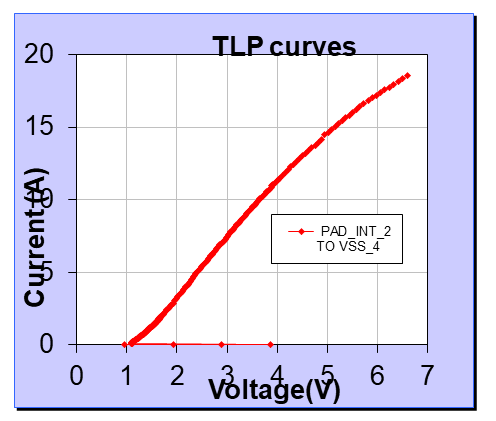
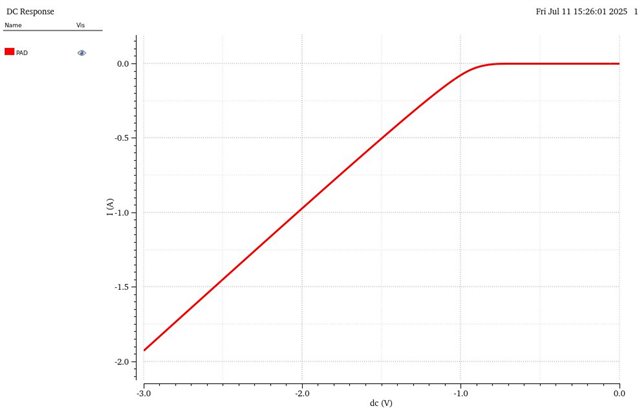
The MDI pins of DP83869HM has a 8kV IEC61000-4-2 contact discharge ESD Rating, I am looking for the spice model of the ESD protection part which is present in the Ethernet Transceiver.
This thread has been locked.
If you have a related question, please click the "Ask a related question" button in the top right corner. The newly created question will be automatically linked to this question.
Hello,
There is no spice model for this device. We do have IBIS models, but this is primarily for SI on the MAC pins. MDI pins are not modeled due to complexity of multi-level swing.
Sincerely,
Gerome
Hi,
Thanks for information, may i know the +ve & -ve clamping voltage on the MDI pins during +-8kV ESD events.
Thanks & Regards
Sudharsan R
Hi Sudharsan,
May I ask how this information will assist in your simulations? Typically if the diodes are activated during this event, this will be enough to protect the PHY from damage. As we have absolute maximum rating, it should be somewhere within that range.
Sincerely,
Gerome
Hi,
We have a requirement to simulate the design on surge events , since you don't have spice model for the ESD protection part we are adding the ESD protection circuit externally to replicate it.
If we know what the Internal ESD +ve & -ve clamping voltage is designed for it will be helpful for selecting the ESD diode. If you have any test data for this this part or similar Ethernet Transceiver part you can share with us.
Thanks & Regards
Sudharsan R
Hello,
I am in discussion with my design folks regarding this topic. Please expect an update by Wednesday next week.
Note: TI US is OoO on holiday next Friday.
Sincerely,
Gerome
Hello,
Thank you for your patience. The ESD behavior may be very difficult to model, but my design team has provided the IV curve of the diodes within the device. Please note that this data may not be the most accurate due to package and board parasitics, but can be used to do relative analysis.

Sincerely,
Gerome
Hi,
Thankyou for going the extra mile efforts in collecting the data, This would be really helpful.
Can you confirm will the IV curve be the same on the -ve voltage as well.
Thanks & Regards
Sudharsan R
Hello,
It is unclear if the IV curve will be symmetric on the -ve side. My team is looking into this, but please expect response next week as US will be OoO for July 4th holiday.
Sincerely,
Gerome
Hello,
My team is looking to regenerate this data for negative strike. Please expect response EoW.
Sincerely,
Gerome
Hello,
Apologies for the delay as E2E was down recently.
Below is the I/V curve for negative DC. Please note this has the same disclaimer of relative analysis only as the initial graph I provided.

Sincerely,
Gerome
Hi,
Thanks for inputs, below are my queries.
1. From the graph i can observe the diode starts conduction around -0.8V. From the data sheet the absolute maximum voltage on the MDI pin is given as -0.5V. So any negative surge between-0.8v and -0.5V can it damage the MDI pins?
2. The clamping voltage from the graph is looking like more than -0.8V, is it need to be less than -0.5V?

Thanks & Regards
Sudharsan R
Hello,
Whenever the voltage exceeds -0.5V, this violates the Absolute Max Rating and opens potential to damage device. I would worry less about how the internal clamping voltage plays around with the absolute maximum and worry about this rating if being meet with consistent signaling (think undershoot/overshoot). Again, this graph is relatively inaccurate due to package and board parasitics.
Sincerely,
Gerome