


Part Number: DP83848I
Tool/software:
Dear TI Support Team.
I am currently designing hardware using the DP83848 Ethernet PHY.
The hardware configuration I intend to implement is shown in the attached diagram.
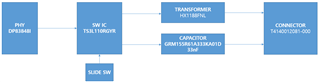
For testing purposes, I am building a setup that allows the selection of the Ethernet communication path using a slide switch.
The slide switch controls the TS3L110RGYR analog switch to select between a transformer path and a transformerless path with DC-blocking capacitors.
Before proceeding with this hardware design, I reviewed the application note AN-1519, which contains a lot of useful information on transformerless Ethernet configurations.
I would like to ask some specific questions regarding the placement of 50Ω pull-up resistors in this design:
- Are there any potential issues or risks with this hardware configuration?
- Are 50Ω pull-up resistors required in the transformer-based path, or are they unnecessary?
- Are 50Ω pull-up resistors strictly required in the transformerless path?
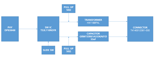
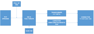
- If both paths require 50Ω resistors, is it acceptable to place a single set of 50Ω pull-up resistors before the TS3L110RGYR, so they are shared between both paths?
The two diagrams below shows the expected placement of the 50Ω resistors.
I would appreciate your advice and clarification.
Best regards.
