A related question is a question created from another question. When the related question is created, it will be automatically linked to the original question.
If you have a related question, please click the "Ask a related question" button in the top right corner. The newly created question will be automatically linked to this question.
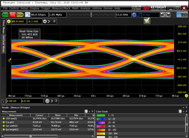
This is an SFP port. The issue is that when using a retimer to transmit a PRBS9 pattern, the resulting signal has problems — the eye diagram test fails. The configuration was applied using the table below, but the eye diagram still has issues. Could you please help confirm whether there is anything wrong with the current settings, or if there are additional configurations that need to be made?
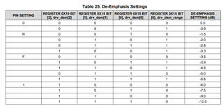
Please configure de-emphasis and VOD to compensate for channel loss between DS110DF111 and the SFP port.
What is your channel insertion loss between DS110DF111 and SFP port? Are you measuring singled-ended signal or differential signal? The VOD looks low for default 600mV setting.
The test signal is differential. The test setup does not include any input signal — it is purely the PRBS9 signal generated by the Retimer. Please help confirm whether the following commands are correct:
For setting de-emphasis to –3.3 dB: i2cset -y 12 0x18 0x15 0x54
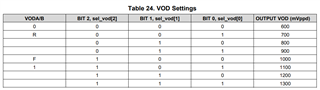
For setting VOD to 1300 mV: i2cset -y 12 0x1b 0x2d 0x87
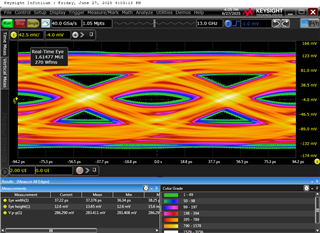
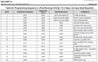
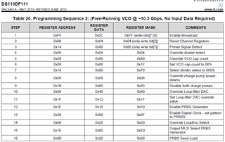
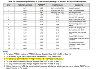
Hi, We are using the DS110DF111 in Free-Running VCO mode, configured to output a PRBS9 pattern. The current measured data rate is 10.58 Gbps, but the expected rate is 10.3125 Gbps. Is there any further adjustment needed to correct the data rate or improve eye diagram performance?
After issuing the command i2cset -y 12 0x18 0x08 0x07, I'm still unable to achieve 10.3125 Gbps. Is there any way to fine-tune it further?
In addition, after adjusting the VOD to 1300 mVppd and setting the De-Emphasis to –3.5 dB, the eye height and Vp-p still appear insufficient. When I increased the De-Emphasis to –12.0 dB, the eye diagram degraded even further. Your assistance would be greatly appreciated. Thank you.
Unfortunately, there is not a way to fine tune the VCO rate further. The free-running VCO is not intended to provide precise data rate. If you require a 10.3125 Gbps signal, you will need to have an input signal for the retimer. Can you supply a 10.3125 Gbps data input to the retimer?
A few questions:
What is the insertion loss between the DS110DF111 and the SFP port?
What specification are you trying to pass? SFF-8418?
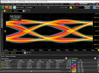
I'm a bit confused by your scope captures. A previous scope capture showed ~1.5Vpp, but this capture shows ~413mVpp. What is the difference between these captures?
The insertion loss between the DS110DF111 and the SFP port still needs to be measured.
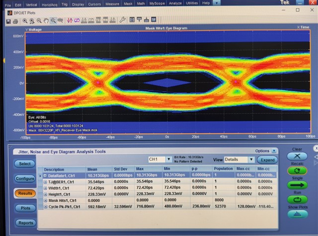
We are conducting tests based on the Ethernet IEEE 802.3 specification, including:
Eye Mask Test
Jitter Test
Voltage Test
Rise Time & Fall Time Test
Jitter Tolerance Test
We're not sure why there is a discrepancy between the waveform measurements. The result showing around 1.5Vpp seems more accurate. Adjusting the VOD and De-Emphasis did not improve the signal.
One more question: If a valid input signal is present, is it still possible to adjust the VOD and De-Emphasis settings? Currently, we are attempting to configure them via I2C, but the write command is not working.
We're not sure why there is a discrepancy between the waveform measurements. The result showing around 1.5Vpp seems more accurate. Adjusting the VOD and De-Emphasis did not improve the signal.
Something seems unusual with your test setup. The signal VOD should be correlated to your VOD setting and de-emphasis setting.
If a valid input signal is present, is it still possible to adjust the VOD and De-Emphasis settings? Currently, we are attempting to configure them via I2C, but the write command is not working.
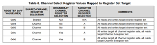
Yes, this is typically how the retimer operates. If you are having challenges with configuration, you might try resetting the channel registers (0x00[2]=1) and then configuring the VOD/de-emphasis to ensure there is not some other register conflict causing an issue.
1.I also observed that devices at I²C address 0x19 and 0x1B return 0xFF = 0x40, which appears to be an invalid or unexpected default. I plan to reset and explicitly configure these before use.
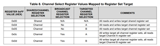
Please let me know if there are any additional precautions I should be aware of when switching register sets.
The current channel configuration is as follows: Channel A: i2cset -y 12 0x19 0xff 0x01 i2cset -y 12 0x1b 0xff 0x01 Channel B: i2cset -y 12 0x18 0xff 0x02 i2cset -y 12 0x1a 0xff 0x02
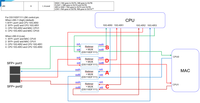
2.As shown in the diagram, the MAC is transmitting a 10 Gbps signal; however, the retimer does not appear to produce any output. Could this be due to a misconfiguration in the retimer settings, or are there other potential causes to consider? Additionally, if Channel A fails to detect a valid input signal, will Channel B still be able to achieve CDR lock independently?
I hope you're doing well. Just wanted to kindly follow up to see if you had a chance to review my previous message. I'd really appreciate your feedback when convenient. Thank you!
1.I also observed that devices at I²C address 0x19 and 0x1B return 0xFF = 0x40, which appears to be an invalid or unexpected default. I plan to reset and explicitly configure these before use.
Please let me know if there are any additional precautions I should be aware of when switching register sets.
The current channel configuration is as follows: Channel A: i2cset -y 12 0x19 0xff 0x01 i2cset -y 12 0x1b 0xff 0x01 Channel B: i2cset -y 12 0x18 0xff 0x02 i2cset -y 12 0x1a 0xff 0x02
2.As shown in the diagram, the MAC is transmitting a 10 Gbps signal; however, the retimer does not appear to produce any output. Could this be due to a misconfiguration in the retimer settings, or are there other potential causes to consider? Additionally, if Channel A fails to detect a valid input signal, will Channel B still be able to achieve CDR lock independently?
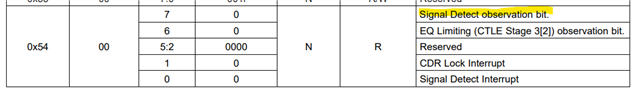
Read 0x02. bit 3 = CDR Lock, bit 4 = Eye/Lock. Re‑validated that 0xFF is reset to 0x00 after each read. All channels currently read 0x00, indicating the CDR has not locked yet.
The MAC is outputting a clean 10 Gbps signal, but the retimer still fails to achieve CDR lock.,