This thread has been locked.

If you have a related question, please click the "Ask a related question" button in the top right corner. The newly created question will be automatically linked to this question.

TUSB321AI: DIR control not working properly, USB3 not working properly

Part Number: TUSB321AI
Other Parts Discussed in Thread: TUSB322, TUSB542, TUSB321

Tool/software:

Hello, 

We are using TUSB321AIRWBR and TUSB542RWQR. 

TUSB is set to UFP mode. 

CC1, CC2 are swapped as mentioned in the TUSB542 datasheet (there is TUSB322, but the logic should be the same as TUSB321, right?)
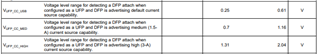
one type-c side:
CC1 => 5V
CC2 => +- 1.8V
DIR => 1.8V => ok

second type-c side:
CC1 => 0V
CC2 => 5V
DIR => 1.8V (should be log. 0?) 


It also works differently on different PC ports and cables (we tried a lot of cables and PCs) 
On Type-C to Type-C connection with a PC, it doesn't even wor,k while with  USB-A to USB-C connection (USB-A is the PC side), USB3 works on one side and USB2 on the other side (mux is not switched). 

First, we thought that the USB connector was not assembled correctly, but now, we have are sure that everything is done well. 

Is there something we might have missed? 

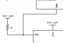
Here are also schematics for the CC controller and the MUX

4478.MUX.pdf

cc controller_edited.pdf

  • I just checked that the board does NOT receive +5V when connected type-C to type-C

  • Hi Jakub,

    I just checked that the board does NOT receive +5V when connected type-C to type-C

    What is not receiving 5V? VBUS or the CC pin? 

    When there is a successful attachment, the voltage on the CC lines so should be within one of the ranges specified above, assuming there is a successful CC connection. 

    one type-c side:
    CC1 => 5V
    CC2 => +- 1.8V
    DIR => 1.8V => ok

    second type-c side:
    CC1 => 0V
    CC2 => 5V
    DIR => 1.8V (should be log. 0?) 

    I believe there should only be one CC pin pull-up, while the other is essentially 0V. There should be no point where both CC pins have voltage on them aside from a DRP configuration where UFP and DFP are toggling.

    For the DIR pin on the TUSB321, I don't see any pull-ups on the pin, which is something we typically recommend:

    Thanks,

    Ryan

  • Hello Ryan, 

    Thank you for your reply.

    What is not receiving 5V? VBUS or the CC pin? 

    When we use type-c to type-c connection, the board does NOT receive VBUS power. 
    When we use type-A to type-c connection (we are type-c), the power is fine. 

    When there is a successful attachment, the voltage on the CC lines so should be within one of the ranges specified above, assuming there is a successful CC connection. 

    I believe we have VUFP_CC_HIGH because it was in this range; however, I could only measure it with a multimeter today, and it was somewhere between 1-1.8V (on the working USB3 side). I will measure it with an oscilloscope on Monday.

    I believe there should only be one CC pin pull-up, while the other is essentially 0V. There should be no point where both CC pins have voltage on them aside from a DRP configuration where UFP and DFP are toggling.

    So the second type-C side is correct? Where on CC1 is 0V, and on CC2 is 5V? 

    For the DIR pin on the TUSB321, I don't see any pull-ups on the pin, which is something we typically recommend:

    R46 is assembled on our board; however, is it really needed? The MUX hasan  internal pull-up on the SEL pin

  • Hi Jakub,

    When we use type-c to type-c connection, the board does NOT receive VBUS power. 

    If the TUSB321 is not seeing VBUS, then it will not believe there is a connection made, as VBUS is used to detect an upstream connection, and is monitored by the VBUS_DET pin. If there is no VBUS, then the TUSB321 will likely fail to see a connection:

    So the second type-C side is correct? Where on CC1 is 0V, and on CC2 is 5V? 

    Yes, this setup for the CC lines is more along what we would normally expect.

    R46 is assembled on our board; however, is it really needed? The MUX hasan  internal pull-up on the SEL pin

    The DIR pin is an open drain pin, so it needs something pulling it up that will also allow the signal to go low if the DIR pin goes low. If the value of the pull-up in the mux does not affect the performance of the DIR pin, then it should be fine. 

    I believe we have VUFP_CC_HIGH because it was in this range; however, I could only measure it with a multimeter today, and it was somewhere between 1-1.8V (on the working USB3 side). I will measure it with an oscilloscope on Monday.

    Yes, please double check this on a working CC connection.

    Thanks,

    Ryan

  • Hi Jakub,

    I am marking this thread as resolved due to inactivity. If you have any questions or need more assistance, feel free to reply here.

    Thanks,

    Ryan