Part Number: TMUXHS4212
Tool/software:
Hi Team
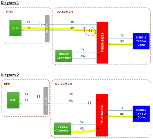
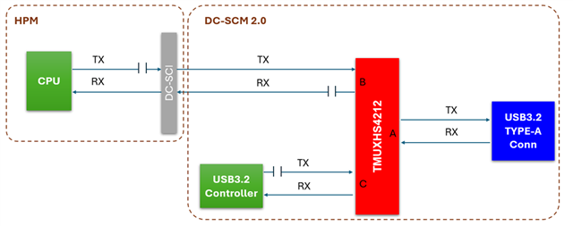
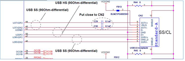
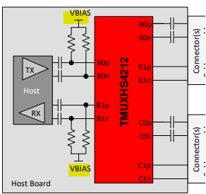
could you help me confirm below placement is correct for customer side?
Our Topology
USB Controller EVB (TX only)
DS topology
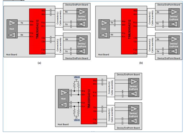
BTW May I know what is the VBIAS meaning and usage here?
BRs
Brian
Original question:

Part Number: TMUXHS4212
Tool/software:
Hi Team
could you help me confirm below placement is correct for customer side?
Our Topology
USB Controller EVB (TX only)
DS topology
BTW May I know what is the VBIAS meaning and usage here?
BRs
Brian