This thread has been locked.

If you have a related question, please click the "Ask a related question" button in the top right corner. The newly created question will be automatically linked to this question.

SN75DP139: 2k can display but 4k can't

Part Number: SN75DP139

Tool/software:

Hi expert,

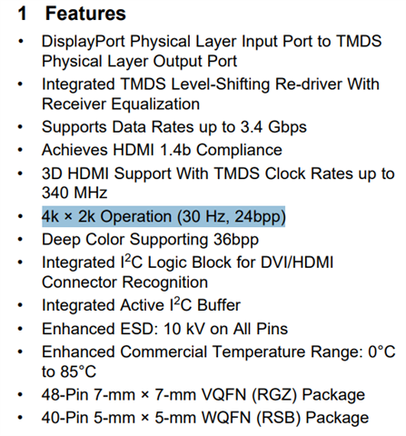
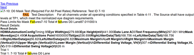
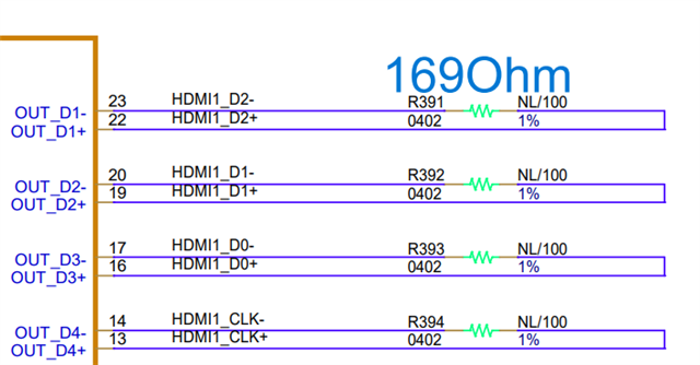
My customer is using SN75DP139 in their system but find it can't display in 4k but can display in 2k. The schematics is 20250707_DMS-BC36_HDMI_DP139.pdf

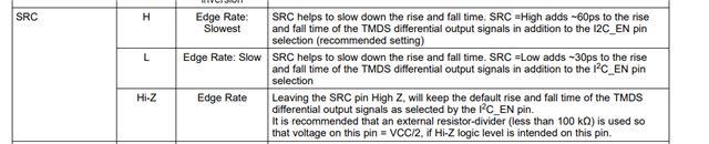
Can you help to check is there any configuration needed when change from 2k to 4k? Or is there any hardware configuration when setting to 4k?

Can you help to review the schematic?

BRs,

Rannie

  • Hi Rannie, 

    DP139 supports HDMI 1.4. HDMI 1.4 can support upto 4K30 so 4K60 will not work. There isn't any hardware configuration on DP139 to output 4K. Is the customer configuring the source correctly to output 4K30? In addition, has the customer run SI test? If so, what was the result and which video timing has they run the test on?

    Best,
    J

  • Hi J,

    Thanks for your reply. What customer tested is 4k@30 and 2k@30. 

    Is the customer configuring the source correctly to output 4K30?

    May I ask how to verify that?

    In addition, has the customer run SI test?

    No SI test.

    So, when customer changing from 2k@30 to 4k@20, the only configuration they need to do is on source side, right? No more configuration needed for redriver itself?

    BRs,

    Rannie

  • Hi Rannie, 

    The customer should be able to measure 297MHz signal on the clock lane. There is no additional configuration needed on the redriver. 

  • Hi J,

    Thanks! I will ask customer to probe the CLK signal.

    Is there any problem for the schematics? Can you help to review?

    BRs,

    Rannie

  • Hi Rannie, 

    Nothing notable on the schematic. There shouldn't be an issue if the customer was able to output 2K. 

    Best,
    J

  • Hi J,

    Thanks for your reply.

    Can you help to check whether the choke BW is OK here?

    BRs,

    Rannie

  • Hi Rannie, 

    Please send me the datasheet on CMC. The schematic does not specify which CMC is used. 

    Best,
    J

  • Hi J,

    Will send it to you tomorrow. Can you help to check what's the minimum bandwidth of this choke on CLK and DATA line?

    BRs,

    Rannie

  • Hi Rannie, 

    We recommend three times the Nyquist frequency of the max bandwidth HDMI 1.4b can support per lane for cutoff frequency. This would be 9GHz. Clock lane wouldn't matter much. If they find CMC to be a concern, they can try replacing them with 0ohm resistor and see if there is any display. 

    Best,
    J

  • Hi J,

    Thanks for your reply. 

    1, Whether SN75DP139 can support 4096*2160@30Hz? I noticed that the HDMI1.4b only support 4096*2160@24Hz and DP139 support HDMI1.4b, can you help to double confirm? What's the meaning of 4K in datasheet?

    2, Customer test SI in 3840*2160@30Hz, the slew rate is too slow. Added R391~R394 will improve the slew rate but the overshoot failed. Can you help to confirm how to adjust it? I noticed in DS that SRC and I2C EN and Vsadj Pin can adjust it.

    BRs,

    Rannie

  • Hi Rannie, 

    HDMI1.4b can support upto 4K30. The meaning of 4K is 4096 pixels. 
    I2C mode in DP139 is read only and does not have any control registers. I suggest lowering the Vsadj resistor to increase the swing to see if that improves the overshoot assuming the SI test is failing because the signal is undershooting by adding extra resistance into the data path. 

    Best,
    J

  • Hi J,

    Thanks for your reply.

    Customer has done the SI test on 3840*2160@30Hz (4k), which shows the D0 mask test is failed. Can you help to check how to optimize the eye pattern?

    The schematics update: SRC=LOW, I2C_EN=HI, R391~R394=169Ohm.


    5228.20250707_DMS-BC36_HDMI_DP139.pdf

    The CMC choke parameter:

    The layout:

    BRs,

    Rannie

  • Hi Rannie, 

    Did the mask test fail before replacing the resistors? If not, I suggest to replace them to 0 ohm resistors and run the mask test again. In addition, could you send me the full SI report on this case and when the resistors are replaced with 0 ohm? 

    Lastly, CMC looks fine according to the specification. 

    Best,
    J

  • Hi J,

    May I ask why customer need change to 0Ohm but not NL?

    BRs,

    Rannie

  • Hi, i missaw the labels. Please run the test NL.

    Best,

    J

  • Hi J,

    Thanks for your quick reply.

    Can you help to elaborate why the terminal resistor should be NL but not 169Ohm? Which performance it will influence?

    BRs,

    Rannie

  • I believe these resistor are put to slow the data rise time, not due to termination. Having such resistor across differential channel impacts signal integrity as the eye mask test shows.

  • Hi J,

    Attachment is the complete SI result with 169Ohm. After removing the 169Ohm, the jitter is worse, and the test also failed so customer test w/ 169Ohm. Can you help to provide some suggestion on how to improve the mask test?

    Whether it would be caused by the layout trace impedance? Customer layout impendence is 100Ohm, but it is 85Ohm in other projects that have passed SI test. In previous E2E discussion, we recommend 100Ohm:(5) SN75DP139: the impendence (?ohm) used for the input and output of the SN75DP139 - Interface - INTERNAL forum - Interface - INTERNAL - TI E2E support forums

     https://e2e.ti.com/cfs-file/__key/communityserver-discussions-components-files/138/4096_5F00_t09_5F00_169_5F00_src_5F00_low.7z 

    BRs,

    Rannie

  • Hi Rannie, 

    Please ask the customer to send us the layout file so we can see the trace length of the differential pair. 
    We are worried if there is too much trace length mismatch that it is showing up as a jitter on the eye diagram and the resistors are compensating for that with the weird pullup to each other. 
    In addition, we would like to know what the output trace length is since it seems like there's too much loss after the redriver that the eye mask is failing. 
    Lastly, has the customer tried using SRC pin to control the edge rate instead of using the resistor?


    Best,
    J