Part Number: TUSB321AI
Tool/software:
I am using a TUSB321AI.
When no power is supplied to the VDD of this device (OFF), will CC1 and CC2 be on the Rd side? Or will they be High-Z?
In other words, when the power is OFF, will it appear to be a UFP device from the other end, or will it be recognized as not connected?
Looking at "7.2 Functional Block Diagram," it appears that there are switches on the CC1, CC2, and Rd paths, and that they are High-Z when the power is OFF.
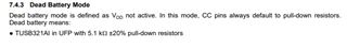
However, "8.3 Initialization Set Up" says the following, so does this mean that Rds is ON when the power is OFF, and that the other end sees it as a UFP?
「1. System is powered off (device has no VDD). The TUSB321AI device is configured internally in UFP mode
with Rds on CC pins.」
Thank you in advance.