Tool/software:
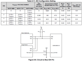
Since the I2C of the image sensor is powered by 3.3V, the I2C of the DS90UB935 is powered by 1.8V. How can the I2C connection between two chips be achieved? If needed, I can provide the schematic diagram. Please help me take a look.
Tool/software:
Since the I2C of the image sensor is powered by 3.3V, the I2C of the DS90UB935 is powered by 1.8V. How can the I2C connection between two chips be achieved? If needed, I can provide the schematic diagram. Please help me take a look.