This thread has been locked.

If you have a related question, please click the "Ask a related question" button in the top right corner. The newly created question will be automatically linked to this question.

DP83TG721S-Q1: TC8 IOP test failed

Part Number: DP83TG721S-Q1


Tool/software:

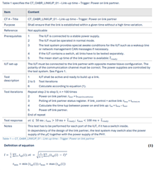
Test IOP part TC 8, the three items regarding link up time do not meet the specifications. All exceed the maximum linkup time.

May I ask if your company has a solution or guidance for corrective measures on this matter?

Testing standard basis: 5.1.2 Link-up time in docs<OA_Automotive_Ethernet_ECU_TestSpecification_Layer_1_100BASE-T1_v3.0.pdf>

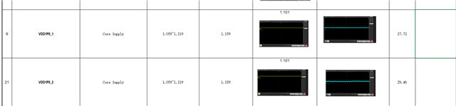
The current test results are as follows:

.........

  • Supplement to test result images:

  • Hi Zewei,

    The DP83TG721 has passed the TC12 linkup time tests during our product validation. I have some questions:

    • TC8 is the test standard for automotive ECUs. I assume the DP83TG721 is being implemented on your own board, is that correct?
    • What is the link partner for the DP83TG721?
    • What register configuration is being written to the DP83TG721?

    Best,

    Evan Su

    • TC8 is the test standard for automotive ECUs. I assume the DP83TG721 is being implemented on your own board, is that correct?
      • yes,DP83TG721 is being implemented on our product 。The product is about to enter mass production, with plans for mass production next month. Currently, there are these failures in the TC8 IOP testing.
    • What is the link partner for the DP83TG721?
      • The testing agency uses Technica's Golden Device product for pairing tests.
    • What register configuration is being written to the DP83TG721?
  • Hello,Is there any update? Including solutions for both software and hardware.

  • Hi Zewei,

    I am in discussions with the rest of our team. Some thoughts so far:

    • As a sanity check, I would recommend manually reading the registers of the DP83TG721 to ensure that the programming sequence in "DP83TG721_cs1_master_init[]" is being successfully applied to the device.
    • If the DP83TG721 is being correctly programmed, we don't have clear reasons from experience why the link up time of the PHY would pass TC12 on the TI board but not pass TC8 in a system.
      • Can you send me your project schematic in private messages so we can review the PHY hardware configuration?

    I searched for the OA materials and the test description seems to be here:

    • Is it confirmed that the polarity of the system is normal?
    • The next linkup test after this one has a different start condition of "power on IUT". Is that test also failing or does it pass?

    Best,

    Evan Su

  • Hi Zewei,

    Thanks for sending me your PHY schematic in private messages.

    I reviewed your TC8 data in more detail. In the first "power on link partner" test that has the most problems, it looks like the passing test iterations have a relatively close spread of between approximately 60-85. The failing test iterations are all much higher than this and there is a slight tendency for failures to be clustered together. So my guess is that there may be an analog, random variable that is contributing to the failure iterations.

    In the schematic, I compared the power supply to our DP83TG721 schematic checklist (available in the DP83TG721 secure resources folder) and found a few details:

    • In your schematic, the net names for the low-voltage core power supply are confusing and I am wondering if the voltage level may be different from what the device is expecting:
      • On this device, pin 29 and pin 9 are VDD1P1, which is a 1.1V power supply like the name suggests.
      • In your schematic,
        • The symbol for the DP83TG721 calls these two pins "VDD_1P0_1/2" - this is not accurate for the DP83TG721
        • The nets connected to the pins are named "VDD1V05_1/2", which sounds like could be 1.05V power rails 
      • According to the DP83TG721 datasheet, 1.05V is the exact minimum bound for the recommended operating conditions of the VDD1P1 power supply. If VDD1P1 is connected to a power supply at a nominal level of 1.05V, any negative fluctuation in the power supply would push VDD1P1 outside of the recommended operating conditions.
      • I suggest that you check the power supply rails , if it is not at 1.1V, it should be set to that level.
    • Also, the low-voltage power supply does not seem to have a large (>= 1 uF) capacitor on the supply side of the ferrite bead as suggested by the schematic checklist structure:
      • I did not see a large capacitor on "VDD1V05" in your schematic.

    Best,

    Evan Su

  • Our electronic engineers have reviewed the schematic based on your suggestions and made the following analysis:

    1 .Pin 29 and pin 9 actually use 1.114V, as shown in the figure below:

    2.Our circuit with the ferrite bead has large capacitance, as shown in the figure below:

    Please check again and consider whether there are other optimization solutions?

  • Hi Zewei,

    The only idea I have for now is to monitor the power supplies (low voltage and others) of the PHY during the test with a high-precision oscilloscope to see if there are any significant fluctuations. I am checking with some internal teams to see if they have additional thoughts.

    Best,

    Evan Su

  • Our electronics engineers gave me some test records from previous LDO output tests. Please check them; they don't seem to have any issues, right?

  • Hi Zewei,

    What is the part number of the PHY which is inside Technica's Golden Device?

    Can you please share how this test is being performed? When does the link up time start? How is the link status monitored?

    Thanks,

    David

  • 1. What is the part number of the PHY which is inside Technica's Golden Device?

         The model is: Marvell 88Q2112。

    2. Can you please share how this test is being performed?

          Technica's Golden Device acts as the link partner, the specific process is outlined in the TC8 3.0 specification.

    3. When does the link up time start? How is the link status monitored?

         The DUT connects to Technica's Golden Device,LINKUP01: Timing starts when Technica's Golden Device powers on the PHY, and stops when the link with the DUT is successfully established.LINKUP02: Timing starts after powering on DUT B, and stops when Technica's Golden Device successfully links with DUT.LINKUP03: Timing starts after powering DUT B and supplying power to ACC while DUT B remains powered, and stops when Technica's Golden Device successfully links with DUT.IOPT Training_Sigent_202108_1000BASE-T1.pdf

  • Hi Zewei,

    Thanks for the information. I will get back tomorrow on this.

    Thanks,

    David

  • Hello David,any update?

  • Hi Zewei,

    Instead of the time between 1) DUT power up and 2) link up, can you measure the time between 1) DUT configuration completed and 2) link up. This is the method for which PHY link up time is measured. This will help us identify which portion of the ECU power up sequence is contributing to the longer link up times. Whether it is the power ramp + configuration time, or whether it is the PHY link up time after the configuration is loaded.

    Thanks,

    David

  • Can you test the LINK UP 1 case on your side? This is a situation where our hardware does not restart, but the link partner restarts. This situation is exactly the case you mentioned. Could your company help us see if there are optimization solutions for this case?

    We are trying to find ways to optimize LINK UP2/3 on our side, but this case will also be interfered with by the phy's linkup event. Therefore, my thought is to first optimize the linkup time1,right?

  • Hi Zewei,

    We have tested this in third party lab, link up time is part of our PHY qualification. We see link up times less than 60ms across thousands of iterations with different link partners. Hence why I am asking regarding the test method.  

    I am wondering if one of the PHYs may be taking a longer time to initialize. It could be that link up time is not a problem, but the initialization time is causing the longer time.

    We recommend the controller to give an indication (a software bit or an IO state) after the last configuration register is written. This indicator going high signals the start of measurement of link-up time.

    If you can share such a measurement, it will help to show whether the link up time is high, or it is the initialization time which is high. We need to understand this to see how to debug further.

    By the way, is the same issue present if DUT is slave? Or if link partner is different?

    Thanks,

    David