Part Number: TUSB321
Other Parts Discussed in Thread: BQ25896
Tool/software:
Hello TI,
I want to confirm, if I understand the behavior of TUSB321 in Sink (UFP) configuration correctly.
My sink device 5V/3A need to check, if sufficiently powerful SOURCE (5V/3A) is connected and then I will enable the VBUS load switch. So, in development beginning, I choose the TUSB321 for this SNK application. Let me know if this is good choice.
According to the TUSB321 datasheet, SNK config must be:
1. CURRENT_MODE - left it floated or? Because this pin is use only for DFP or DRP mode. I didn't find any information in datasheet how to connect this pin, when PORT = LOW (UFP).
2. PORT - connected to GND (Because I want only UFP mode)
3. VBUS_DET - connected through resistor to the load switch output
4. ID - this pin is not active in sink(UFP), right? So, I need to control the load switch different way. I want to use OUT1/OU2 pins
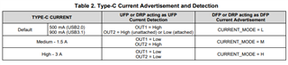
5. OUT1/OU2 - these pins report the source current capability, right? If the high current source (3A) will be connected, then both OUTx pins will be LOW (Table 2). So, I want to connect both OUTx pins to OR gate inputs and when both OR inputs will be LOW, then OR output will be LOW and turn ON the VBUS load switch.
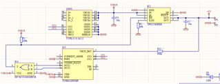
Please, check if my circuit is correct.
Thanks
Best regards,
Martin