This thread has been locked.

If you have a related question, please click the "Ask a related question" button in the top right corner. The newly created question will be automatically linked to this question.

THVD1450: Output Signal Distortion When Using THVD1450DR

Guru 12235 points
Part Number: THVD1450

Tool/software:

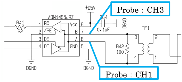
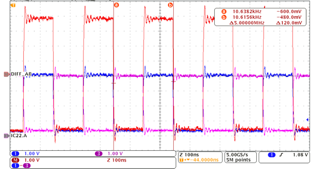
We are currently evaluating THVD1450DR as a replacement for the ADM1485JRZ and have observed waveform behavior during transmission testing.
When using THVD1450DR, we noticed significant overshoot and undershoot on the A/B differential outputs, which raises concerns regarding signal integrity.

Based on our initial analysis, we suspect the following potential causes:

  • The strong driver strength of THVD1450DR may be causing signal reflections due to mismatched termination or transformer characteristics.

  • The transformer (TF1) may be contributing to the issue due to its leakage inductance or limited frequency response.

  • The existing 100Ω termination might not match the differential impedance, or single-sided termination could be insufficient.

  • PCB layout mismatches such as improper differential pair routing or poor return paths may be worsening the effect.

  • The measurement method (standard probe setup) might also exaggerate ringing due to probe inductance.

We would greatly appreciate your feedback on these observations and any additional considerations you may recommend.

Thanks,

Conor

  • Hi Connor,

    • The strong driver strength of THVD1450DR may be causing signal reflections due to mismatched termination or transformer characteristics.

    • The transformer (TF1) may be contributing to the issue due to its leakage inductance or limited frequency response.

    • The existing 100Ω termination might not match the differential impedance, or single-sided termination could be insufficient.

    • PCB layout mismatches such as improper differential pair routing or poor return paths may be worsening the effect.

    • The measurement method (standard probe setup) might also exaggerate ringing due to probe inductance.

    I agree with everything stated as potential issues to ringing. The main difference I see between the comp device and our device is the slew rate is faster on ours which would generate a different frequency response. Comp has typical rise/fall as 8ns while ours is 2 ns, so there is more energy during the edge rate transitions. This could have an effect with the transformer being used since it looks like a higher frequency which the transformer may try to resist more (due to it's inductance).

    What you could also try is placing a differential cap in parallel (you can just solder it ontop of the 100 ohm termination resistor) which could help to smooth out the ringing since it would slow down the edge rate. 

    -Bobby

  • Hi Bobby,

    so there is more energy during the edge rate transitions.

    Could the issue be related to a mismatch between the characteristics of our currently used pulse transformer (TF1) and the high slew rate of THVD1450DR?
    Would replacing the transformer with one that is better suited for higher edge rates help reduce the ringing?

    What you could also try is placing a differential cap in parallel (you can just solder it ontop of the 100 ohm termination resistor) which could help to smooth out the ringing since it would slow down the edge rate. 

    Regarding the differential capacitor placed in parallel with the 100Ω termination resistor:
    In our design, the 100Ω termination resistors are located both at the driver (transmit) side and at the far end of the transmission line.
    Which side should we place the capacitor on for the most effective suppression of the overshoot/undershoot observed at the driver output?

    Could you suggest an appropriate range of capacitance values for this differential capacitor? This would help guide our testing.

    As a possible alternative to THVD1450DR, is there a TI device with similar characteristics to ADM1485JRZ, and with pin compatibility?

    Thanks,

    Conor

  • Could the issue be related to a mismatch between the characteristics of our currently used pulse transformer (TF1) and the high slew rate of THVD1450DR?
    Would replacing the transformer with one that is better suited for higher edge rates help reduce the ringing?

    It probably would make a difference if you changed the transformer. I think of the transformer like an inductor, there is going to be some frequency the inductor would want to resist the frequency change. Though I think trying to add the differential cap may be easier to modify. 

    In our design, the 100Ω termination resistors are located both at the driver (transmit) side and at the far end of the transmission line.

    Is the RS485 transceiver switching between transmitting and receiving? Or is this transmit side only transmitting and never acting as a receiver node? We normally tell customer to place resistors on both sides when the nodes can/will switch from transmitter to receiver. If one node is always transmitting and one node is always receiving then you will typically get better signal quality by putting the termination resistor on the receiver node only.

     Though, in your scopeshot, it seems like the signal output swing looks good even with the termination resistor on the driver side.

    Could you suggest an appropriate range of capacitance values for this differential capacitor? This would help guide our testing.

    I would experiment with this a bit. This is kind of a balancing act. If you place too much capacitance, your max signal rate and the distance is can communicate will shorten so you don't want to go crazy and add too much cap.

    I would probably start off with 100pF or 200pF. After see if the overshoots are weakening. If not, add another 100pF or 200pF and repeat. Send the fastest alternating byte you need to support (0b0101 0101 or 0b1010 1010) to see if the bit period is being squeezed too much by the added cap. 

    As a possible alternative to THVD1450DR, is there a TI device with similar characteristics to ADM1485JRZ, and with pin compatibility?

    https://www.ti.com/product-category/interface/rs-485-rs-422-transceivers/products.html#993=1&994=1&1065=Half&976max=30%3B35&0nom=5%3B5&

    I filtered based on half duplex, min data rate 30Mbps to 35Mbps max, with Vcc=5V and 1 transmitter/ 1 receiver

    seems like SNx5ALS176x would be the right family. 

    Or maybe you can tell me the max data rate you need to support and we can try hit that instead of 30Mbps. 

    -Bobby