This thread has been locked.

If you have a related question, please click the "Ask a related question" button in the top right corner. The newly created question will be automatically linked to this question.

TL16C754C: TXB Output Problem

Part Number: TL16C754C
Other Parts Discussed in Thread: TL16C754B,

Tool/software:

Hello,

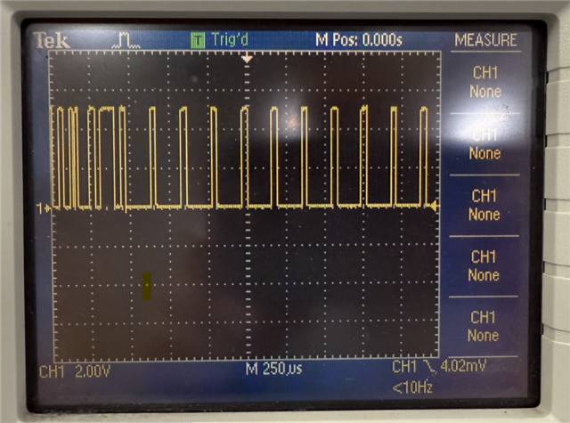
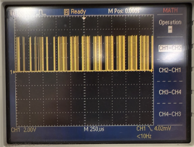
We recently swapped out TL16C754B with TL16C754C on one of our PCBs.  As none of the registers changed between the two, we did not make any changes to the firmware (Note: we are not using the Alternate Function Register).  When testing the PCB, we found that there was an issue with the data being transmitted from UART B.  We took oscilloscope captures of the output of TXA and TXB (referenced to ground), as you can see in the pictures, the TXB waveform has a much higher frequency than the TXA waveform.  We should expect to see the same waveform transmitted on TXA and TXB.  Are there any changes between TL16C754B and TL16C754C that would affect the baud rate generator for UART B?  Are there any other changes that could be causing this issue?

  • Hi McCabe,

    Does your code write to the MCR register for both A/B channels to set the pre-scaler?

    Are you able to read the MCR register for the B channel?

    -Bobby

  • Hi Bobby,

    Thanks for the reply!  Yes, we write to the MCR register for both A/B channels.  Also, I wanted to provide some additional information.  On the previous PCB, we had the INTSEL pin connected to AT89C51ED2 P3.5 - on the new PCB both of these connections are left open since INTSEL is now pulled up internally in TL16C754C.  In our code we still define INTSEL as we didn't make any changes to the firmware.  Would we need to remove that INTSEL define?  Also, since the INTSEL pin has been removed, what changes would we need to make to the firmware to implement that functionality using the MCR register?

  • on the new PCB both of these connections are left open since INTSEL is now pulled up internally in TL16C754C.

    Please note our device table 1 states this pins is internally pulled down (not pulled up). You need to write to MCR to control this now. 

    Please also note, my previous question was in regards to the CLKSEL (pin 21). I think the issue that you are seeing is that the MCR7 differs between CHA and CHB where you likely have one of them dividing the clock by 4 and the other by 1 so you end up with different buad rates.

    In our code we still define INTSEL as we didn't make any changes to the firmware.  Would we need to remove that INTSEL define?  Also, since the INTSEL pin has been removed, what changes would we need to make to the firmware to implement that functionality using the MCR register?

    You should be able to write MCR3 and set it to 1 if you need the IRQ outputs. 

    Accessing MCR3 only requires LCR !=0b1011 1111

    If you need to access MCR7, this requires an additional change to set EFR4 to access MCR7. 

    -Bobby

  • Please note our device table 1 states this pins is internally pulled down (not pulled up). You need to write to MCR to control this now. 

    Please also note, my previous question was in regards to the CLKSEL (pin 21). I think the issue that you are seeing is that the MCR7 differs between CHA and CHB where you likely have one of them dividing the clock by 4 and the other by 1 so you end up with different buad rates.

    Ah okay, that makes more sense that it is pulled down internally - also, thank you for the response regarding MCR3 for the IRQ outputs.  As for the prescaler - we write to MCR7 for both CHA and CHB, they are both set to 1.  Also, we write to DLL and DLH - is there anything else that could potentially affect the baud rate?  Something that would specifically affect UART B.  The firmware did function properly with TL16C754B.  

  • Also, one thing we noted is that we measured TXA and TXB with just power supplied to the PCB - according to the datasheet, TXn should be high when no data is being sent.  We had a logic high on TXA, but low on TXB.  We also tested a card that wasn't flashed, and that one measured logic high on both TXA and TXB as expected.

  • we write to MCR7 for both CHA and CHB, they are both set to 1.  Also, we write to DLL and DLH - is there anything else that could potentially affect the baud rate?  Something that would specifically affect UART B.

    Is it possible for you to do a register read and verify the writes are correct? 

    Something that would specifically affect UART B.  The firmware did function properly with TL16C754B.  

    I remember there was an issue for some customers that went from B to C.... 

    TL16C754C has an upgrade which includes an AFR (485 control mode). This put a restriction on access to FCR (LCR7 must be 0) whereas the B version did not have this restriction. So backwards compatibility was not guaranteed when moving from B to C using B firmware. In this case, sometimes customers would think they are reading IIR but read AFR or EFR.

    I don't think this applys to you since the problem isn't related to FCR/IIR or the EFR/AFR.

    TXn should be high when no data is being sent.  We had a logic high on TXA, but low on TXB.

    This sounds like the LCR bit 6 is set to '1' on channel B indicating it's enforcing a break condition on the bus. Can you read LCR CHB to verify its contents when TXB is low? 

    -Bobby

  • Is it possible for you to do a register read and verify the writes are correct?

    I can establish a serial connection with the board, but we have fairly limited commands (i.e. just reading the serial number, and a few debugging commands).  I don't believe we can read the registers from there - is there any other way for use to read the registers?

  • I confirmed that we do not have a way to read the registers.

  • Hi McCabe,

    I confirmed that we do not have a way to read the registers.

    This makes it a bit difficult to debug since we don't have a clear way to really verify if the writes are being accepted like what we would expect.

    is there any other way for use to read the registers?

    Only other way I could think to do this is manually, which may not be possible if you can't set your processor to be tri-state after initializing the UART device. It would also take a bit time of and may require a bit of blue wire on the interface pins. 

    Can you probe the CLKSEL pin and see if it ever changes?

    Can you also include the #RESET pin on the same scope and see if CLKSEL is ever a different state when #RESET is toggled?

    (We also want to verify the reset pin gets toggled)

    The only thing that makes sense to me is that the prescaler is not the value it should be or DLL/DLH aren't the write values (or both) but I'm leaning towards the prescaler. If your code doesn't write to MCR7 or it does but then for some reason toggles reset after then that might explain it. 

    -Bobby

  • Can you probe the CLKSEL pin and see if it ever changes?

    Can you also include the #RESET pin on the same scope and see if CLKSEL is ever a different state when #RESET is toggled?

    (We also want to verify the reset pin gets toggled)

    I will check these and get back to you - in the meantime I had a quick question on MCR7:

    If your code doesn't write to MCR7 or it does but then for some reason toggles reset after then that might explain it. 

    If we didn't write to MCR7, wouldn't it just default to setting the prescaler to 1?

  • If we didn't write to MCR7, wouldn't it just default to setting the prescaler to 1?

    You're correct. It should.

    There are cases where I'm not 100% sure if it would though:

    Maybe a bad power on reset (PoR) like too slow ramp up or too fast ramp up or brownout before power up could result in the internal registers could go to unexpected values.

    Unexpected noise/voltage coupling onto CLKSEL or a non-monotonic reset edge. 

    -Bobby