Part Number: DS90UB960-Q1
Other Parts Discussed in Thread: DS90UB933-Q1, DS90UB913A-Q1, ALP
Tool/software:
Hi Team,
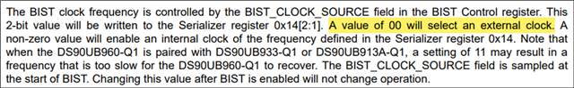
I'm working with a camera using a 933 SER and connecting it to a 960EVM while attempting to run BIST. In doing so, I noticed that my BIST runs always fail when I set the BIST_CLOCK_SOURCE to use the external clock from the SER:
However, if I modify the BIST_CLOCK_SOURCE to leverage the internal clock, it will successfully run with any of the modes shown in green below.

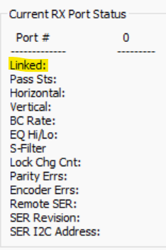
From the datasheet snippet above, there is a comment stating that "when the DS90UB960-Q1 is paired with DS90UB933-Q1 or DS90UB913A-Q1, a setting of 11 may result in a frequency that is too slow for the DS90UB960-Q1 to recover". Given this, I'm wondering if my external clock is too slow for BIST operation on this camera. I'm currently looking to get the schematic and/or confirmation on the external clock used in this design, but when I connect and view the information tab of ALP, I'm seeing that I'm linked at 33-MHz.
Are their any limitations on minimum speed for the BIST_CLOCK_SOURCE when pairing a 933 with a 960?
For reference, here's the BIST script I've been using:
import usb2any_lib as USB2ANY
import math
import time

desAddr = 0x7A
serAlias = 0x18

board = USB2ANY.Board()

board.WriteI2C(desAddr, 0x4C, 0x12)     # Select Port 0
board.WriteI2C(desAddr, 0x58, 0x58)     # Enable I2C pass-through and set back channel to 2.5 Mbps for operation with 933/913
board.WriteI2C(desAddr, 0x5C, serAlias) # Set Serializer Alias

print("Deserializer Address: " + str(hex(board.ReadI2C(desAddr, 0x00))))
print("Serializer Address: " + str(hex(board.ReadI2C(serAlias, 0x00))))

duration = 10 # Duration for BIST in seconds
t_end = time.time() + duration

# Force FC BIST errors
# board.WriteI2C(serAlias, 0x13, 0x81) # Forcing 1 error

# Enable BIST
board.WriteI2C(desAddr, 0xB3, 0x05) # 0xB3[2:1] controls the BIST clock source used by the SER. 00 = External Clock, 01 = Internal Clock: 100-MHz (RAW10) or 75-MHz (RAW12), 10 = Internal Clock: 50-MHz (RAW10) or 37.5-MHz (RAW12).

time.sleep(0.1)

SER_BIST_ACT = (board.ReadI2C(desAddr, 0xD0) & 0x20)

if SER_BIST_ACT:
  print("BIST was properly activated")
else:
  print("BIST was not properly activated")

while time.time() < t_end:
    pass

board.WriteI2C(desAddr, 0xB3, 0x00)
des_err_count = board.ReadI2C(desAddr, 0x57)
print("Deserializer Error Count: " + str(des_err_count))

def confidence_level(t, data_rate, errors):
  BERs = 1e-10
  transmitted_bits = data_rate * t
  temp_array = []
  errors += 1

  # Proper Confidence level calculation in Python is bounded by the following requirement:
  #     (transmitted_bits * BERs)**errors >= 1.76e+308
  # If this condition is not met, an overflow error will occur due to 64-Bit Python 3 being limited to ~1.8e+308 as a max value.
  if (transmitted_bits * BERs)**errors >= 1.76e+308:
    confidence = 'Error - Confidence calculation failed due to Python limitation, please manually calculate confidence'
    return confidence
  else:
    factorial = 1
    for k in range(0, errors):
      if k > 170:
        factorial = 7.257416e306
      else:
        for j in range(1, k+1):
          factorial = factorial * j

      temp_array.append(((transmitted_bits * BERs)**k) / factorial)
      factorial = 1

    confidence = (1-((math.exp(-transmitted_bits*BERs)) * sum(temp_array)))*100

    if confidence < 5e-09:
      confidence = 0

    return confidence

data_rate = 4e9 # Data rate dependent upon 954/960 REFCLK. See Table 6-8 of 953 datasheet for FC data rate calculation

confidence = confidence_level(duration, data_rate, des_err_count)
print("Confidence Level: " + str(confidence) + "%")
Regards,
- Andy