This thread has been locked.

If you have a related question, please click the "Ask a related question" button in the top right corner. The newly created question will be automatically linked to this question.

TPS546D24S: TPS546D24S >Vout max issue using TI Fusion digital power design

Part Number: TPS546D24S

Tool/software:

HI,

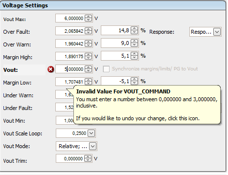
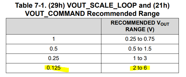
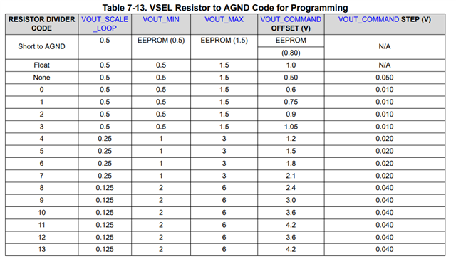
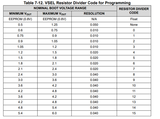
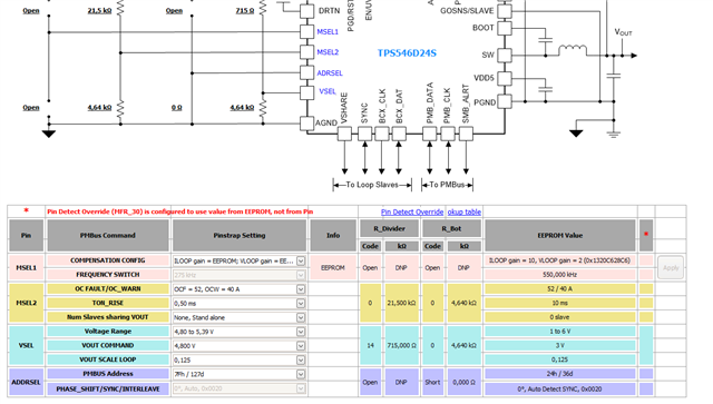
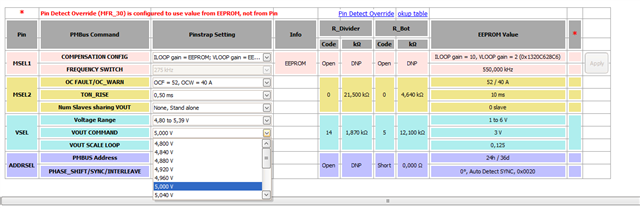
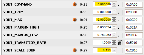
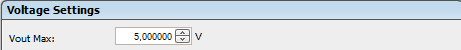
I am using TPS546D24S chip which can go up to 5.5V Vout (i changed the Vout max to 5v)  but when i tried to change the Vout its giving me an error and showing that you could go maximum up to 3V.

Even though the software detects the right chip part number.

Also, how to correct this by sending I2C command using TI fusion digital power?

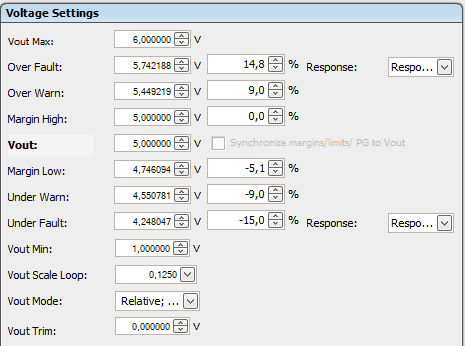
Please help me what i could do in order to test the IC full potential.

Thanks in advance !

Regards

Salman

  • Hi Salman,

    The VOUT_MAX command sets an upper limit on the output voltage the unit and can command regardless of any other commands or combinations. The intent of this command is to provide a safeguard against a user accidentally setting the output voltage to a possibly destructive level.

    Since you have set the VOUT_MAX to 5V, you will not be able to set the output voltage higher than 5V. In order to set to 5.5Vout, you will need to set it VOUT_MAX greater than 5.5V, and it can go as high as 6V. 

    Thank you,
    Tomoya

  • Yes, i totally get that but the problem is that i cannot go above 3V, its showing me its not possible to put a value more than 3V

    The limitation is set by the software i have to change some setting in the software so it will allow me to put a higher value than 3V as Vout.

  • Hi Sal,

    You would need to set the VOUT_SCALE_LOOP to a lower value of 0.125. 

    Thank you,
    Tomoya

  • It worked in configuration side but in reality io cannot go more than 3v and less than 1v

    Having these errors

  • I know using VSEL MSEL1 resistors we choose the value for Vout threshold but i thought using I2C i can go to full scale 0.5v-5.5v seems like if i change the resistor code only then i can play around that Vout bracket

    1-3v

    0.5-1v

    2-6v


    Is that so?

  • Hi Sal,

    The device is selectable from 0.5V to 5.5V output via pinstrap or 0.25V to 5.5V using PMBus VOUT_COMMAND.

    When you changed VOUT_SCALE_LOOP, did you disable the converter? VOUT_SCALE_LOOP only allows updates on-the-fly when conversion is disabled. Write to this register will be blocked if conversion is enabled, so you want to make sure the converter is disabled if you want to make changes on-the-fly.

    Also, if you are using EEPROM instead of Pin Detection, you would need to specify this in the PIN_DETECT_OVERRIDE. If you had set VOUT_COMMAND/VOUT_SCALE_LOOP to "reset to pin-detect value at power up or RESTORE", the device resets to pin-detected value after power cycle. You'd want to change this to "reset to NVM..."

    Thank you,
    Tomoya

  • No i dont disable the converter

    Moreover i want to ask if this Pin strapping is just for knowledge to know for which configuration which resistor i will use or i actually select the options and override it to the IC?

    Because here i can select the desirable output i want but it didn't change anything anyway

    Here are the snapshot (schematic) of the divider resistors i am using:

    ADRSEL is floating (resistor not mounted)

    Thanks in advance

    Sal

  • Hi Sal,

    Moreover i want to ask if this Pin strapping is just for knowledge to know for which configuration which resistor i will use or i actually select the options and override it to the IC?

    The Pin Strapping tab is more for information to provide customer what resistor values to use. For MSEL1, you can click on "Apply" button, which will update the COMPENSATION_CONFIG and FREQUENCY_SWITCH registers in the GUI on other tabs.

    Based on your pinstrap resistors on your schematic,

    VSEL:

    • Voltage Range: 1.80 to 2.09V
    • VOUT COMMAND: 1.800V
    • VOUT SCALE LOOP: 0.25

    MSEL2:

    • OC FAULT/ OC WARN: OCF=52A, OCW=40A
    • TON_RISE: 10ms
    • Stand-alone

    If you have any further questions, please feel free to reach out directly at t-ide@ti.com. We can also set up a call if needed.

    Thank you,
    Tomoya

  • Hi,

    Thank you for the previous information. I'm already familiar with the parameters you mentioned, as I was the one who designed the schematic.

    My current issue is with controlling the VOUT using PMBus. In the software (TI Fusion Digital Power Designer), I’ve configured the VOUT up to 5 V, but in reality, the output doesn’t change beyond 3 V. I initially assumed the resistor divider was restricting the IC’s output range, but that doesn’t seem to be the root cause. It now appears that the physical pin configuration is playing a greater role than expected.

    To summarize: I’d like to use only PMBus software commands to configure the TPS546D24S VOUT between 0.5 V and 5.5 V without needing any hardware changes (e.g. adjusting resistor values for VSEL, MSEL1, etc.). Could you please guide me through the proper steps or confirm if this is possible?

    Kind regards,

    Sal

  • Hi Sal,

    Sure! Here are the steps for configuring the device to 5Vout:

    1. Ensure that there is input voltage to power the device, but keep CONTROL low to prevent any converter activity during configuration.

    2. In the Fusion GUI, you will need to change the following settings: - VOUT_COMMAND - VOUT_MAX - VOUT_SCALE_LOOP

    3. After making these changes, click "Write to Hardware" to save the changes.

    4. Enable the converter by bringing CONTROL high. You should see the output voltage power up to 5V.

    5. (Optional) If you want to configure the device to always powers up to 5V, regardless of the pin strap on VSEL, change the PIN_DETECT_OVERRIDE to 0x1B2E. Write this to hardware and then click "Store Config to NVM" to execute STORE_USER_ALL. This will ensure the device resets to the NVM value rather than the pin-detect value.

    Thank you,
    T
    omoya

  • Sorry my USB-TO-GPIO was not working i have bought a new one and it worked thanks