This thread has been locked.

If you have a related question, please click the "Ask a related question" button in the top right corner. The newly created question will be automatically linked to this question.

TCAN1145-Q1: CAN Waveform

Part Number: TCAN1145-Q1

Tool/software:

Hi team,

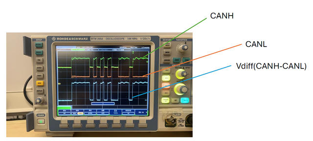
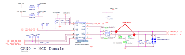
My customer are using TCAN1145DMTRQ1 for their project, when they test the CAN bus waveform, the result looks abnormal. Can you please help analysis the reason? Thank you

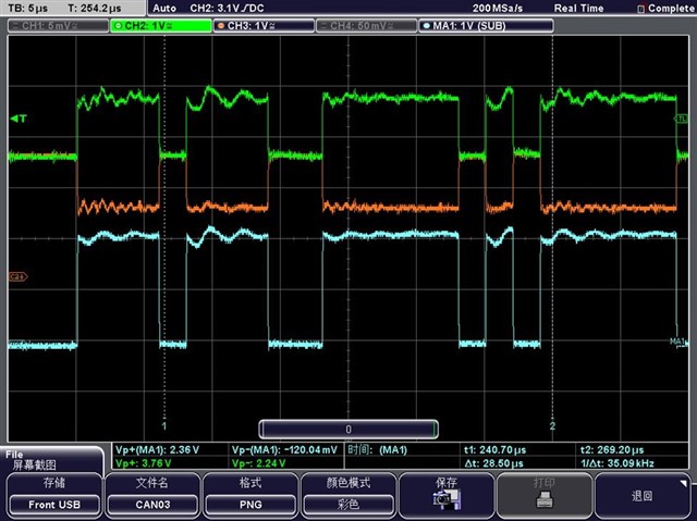
They use the 120R terminal resistor at the end of CAN bus cable when operate the test.

Best Regards,

Xiaowei Zhang

  • Hi Xiaowei,

    What are the green, orange and blue signals? Can they add some labels? 

    What is the exactly the issue they mentioned here? Did they see error bit or something else?

    Regards,

    Sean

  • Hi Sean,

    Waveform with label as below:

    Test Summary: Joynext_VF_TCAN1145-Q1_CANBUS_ISSUE.pdf

    What is the exactly the issue they mentioned here? Did they see error bit or something else?

    Not yet, but they are currently conducting the test in the laboratory environment, not on the vehicle. The current waveform problems haven't effect the CANBUS communication as severely as they concerned. But they worried that the situation on the vehicle will be even worse. So they want to optimize the waveforms on the CANBUS.

    So can you please help provide some suggestion for the waveform optimize? Thank you

    Best Regards,

    Xiaowei Zhang

  • Hi Xiaowei,

    Those waveforms are actually good, the differential voltage drives dominant and recessive state correctly, that being said, I don't expect the communication will fail on the vehicle, it may only affect the EMC performance.

    It is recommended to place at least 100 nF decoupling capacitor near the supply pins as close as possible, looking into their test report, adding 10uF close to VCC pin improves the signal. Ringings are usually caused by impedance mismatch due to improper termination. Even if they've added 120 Ohms at the end of cable, they still need to populate the terminations on the board. I would recommend them populating two 60 Ohms terminating resistor and 4.7nF split capacitor to ensure the overall bus termination is 60 Ohms (with that 120 Ohm on the end), a proper termination is still required on ECU-level testing.

    Their differential CAN traces take asymmetrical paths on the layout. Different trace lengths will result in the differential signal traveling at different times through the traces. This can induce more coupling to other signals and reduce noise immunity as the differential signal is compromised where the transition travels along the traces. Recommend keeping signal traces close to the same length, minimizing the offset that is added during turning by keeping the traces close together. Try to keep the number of left-turns and right-turns even to reduce length mismatch. If needed, use signal stitching to matching lengths of CAN signals.

    Regards,

    Sean

  • Hi Sean,

    Thanks for your support.

    Customer asked from their test result, why the capacitance of the VCC input capacitor affects the waveform of CANBUS. 

    After detailed check their SCH, seems the CAN bus oscillate is cause by insufficient VCC bypass capacitor.   

    Best Regards,

    Xiaowei Zhang

  • Hi Xiaowei,

    CAN driver is referenced to VCC, so it requires VCC have enough decoupling, that's why we have power supply recommendation in the datasheet.

    Regards,

    Sean