This thread has been locked.

If you have a related question, please click the "Ask a related question" button in the top right corner. The newly created question will be automatically linked to this question.

DS90UH983-Q1: The output of port1 shows indistinct black stripes

Part Number: DS90UH983-Q1

Tool/software:

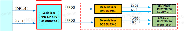
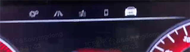
The second screen of the ti983 output has a probability of regular black vertical stripes, which can only be found by looking closely, the other screen is good, no picture for the time being, I'll add a picture later, the ser-pattern also shows black stripes, is there any direction for troubleshooting or registers that can be analyzed, thank you!

  • Hi Ian,

    If the serializer pattern generation also shows stripes, then this could be related to the programmed timing not matching the display timing. Could you please check that these display timings match.

    As a next step, you could also try deserializer PatGen. Which deserializer are you using with the 983? By programming the deserializer to output the test pattern, this will isolate it from the serializer, and video will only depend on the DES configuration and downstream connection to the display panel. Please let me know if you need any support on this.

    Best regards,
    Ikram

  • HI Ikram,

    Thank you for your reply. There were some things that I didn't reply to in a timely manner last week, deserializer is ti948, How to use patgen with this deserializer?

  • Hi Ian,

    Could you share your topology as a diagram to show how the UH983 is connected to the 948 and any other deserializers. This will help to clarify your configuration.

    For 948 deserializer pattern generation, you can use the Analog LaunchPad software by connecting to the 948 and programming the pattern generation with the specific display settings.

    Could you also please check the CRC error count registers and probe the LOCK pin on the deserializer to check whether there are any loss of LOCK during operation.

    Best regards,
    Ikram

  • HI Ikram,

    The chart format is as follows:

    I have tried using Analog LaunchPad software to generate the patgen of the deserializer, but in reality, I only saw the pattern of the deserializer being generated. Can you help me generate a copy with the following timing? Thank you!

  • Hi Ian, 

    For the files and tools to program the device please reach out to your local TI FAE to support this request. 

    Best regards,
    Ikram

  • Hi Ikram,

    I verified locally that our screen has automatic initialization. After disconnecting the screen power and then re powering it, the screen corresponding to port1 still has black stripes, and the screen corresponding to prot0 has not encountered any problems. The normal and abnormal images are as follows. In addition, when writing 0x01 to the 0x01 register of the adder, the black vertical bar on the screen corresponding to prot1 disappears. I think the problem lies with the adder

    normal

    abnormal

  • Hi Ian,

    Are the black stripes gone and the issue is resolved? 

    In addition, when writing 0x01 to the 0x01 register of the adder, the black vertical bar on the screen corresponding to prot1 disappears.

    Which device and register is this for? Could you please tell us what is the adder you are referring to here?

    Best regards,
    Ikram

  • Hi Ikram,

    Are the black stripes gone and the issue is resolved? 

    -->Sorry, I didn't describe it clearly before. It's a black vertical bar

    I apologize for any inconvenience caused by the previous description. Let me rephrase it. The pattern of ti983 also has regular black vertical bars. By writing 0x1 to the 0x01 register of ti983, the black vertical bars in the pattern of 983 can disappear. Do you have any troubleshooting directions next

    Now it is a dual screen display method. Currently, the screen corresponding to Port0 has not encountered any problems, but the screen corresponding to Port1 may occasionally experience this issue

    board.WriteI2C(serAddr,0x2d,0x1) #Select FPD TX Port 0

    board.WriteI2C(serAddr,0x57,0x0) #Set FPD TX Port 0 Stream Source = VP0

    board.WriteI2C(serAddr,0x2d,0x12) #Select FPD TX Port 1

    board.WriteI2C(serAddr,0x57,0x0) #Set FPD TX Port 1 Stream Source = VP0

    board.WriteI2C(serAddr,0x5b,0x2b) #Enable FPD III FIFO

  • Hi Ian,

    If you do a soft reset to the 948 deserializer by setting register 0x1 = 0x1, does the issue also go away? Does it also go away if you PDB reset the DES?

    Please also check the the 948 datasheet "9.2 Power Sequence" for the initialization sequence.


    If the resolutions are the same (1920x720), if you switch the port 0 and Port 1 outputs between the two displays, does the issue show follow Port 1 or the panel?

    Best regards,
    Ikram

  • Hi Ikram,

    The screen side has its own MCU that will power on and initialize the Ti948, and the same abnormal phenomenon occurs when the screen side is powered off and then powered on again. Therefore, I think the problem lies with the Ti983 side

  • Hi Ikram,

    If the resolutions are the same (1920x720), if you switch the port 0 and Port 1 outputs between the two displays, does the issue show follow Port 1 or the panel?

    --->The problem occurred in Port1

  • Hi Ian,

    So you have two display panels with 948 DES on each, let's call them Display_0 and Display_1.

    983 SER Port0 -> Display_0
    983 SER Port1 -> Display_1

    1. Since Port1 -> Display_1 shows the issue. Since the display resolutions are same, if you switch the displays (as below), does it follow the port or display?

    983 SER Port0 -> Display_1
    983 SER Port1 -> Display_0

    2. If you soft reset the SER, by settings register 0x1 - 0x1, the issue goes away. Is this correct? You mentioned this before, but I just wanted to confirm.


    3. What the MODE_SEL settings on the 948? Could you please check the schematic or read 948 DES register 0x37. This could be related to OLDI dual port swap.

    4. When you try with 983 pattern generation, are there black vertical lines as well? Please send a photo if possible.


    I have also sent you a request, please accept it so I can message you with my email. Since the 983 parts are not fully public, it would be best to continue the conversation over email.

    Best regards,
    Ikram


  • Hi Ikram,

    1. Since Port1 -> Display_1 shows the issue. Since the display resolutions are same, if you switch the displays (as below), does it follow the port or display?

    --->He is following the port

    2. If you soft reset the SER, by settings register 0x1 - 0x1, the issue goes away. Is this correct? You mentioned this before, but I just wanted to confirm.

    --->By writing 0x01 to the 0x01 register of ti983, it was observed that the black vertical bar in the pattern of t983 disappeared. However, when the pattern was turned off, there was no display because the setting of the APB register would be clear

    3. What the MODE_SEL settings on the 948? Could you please check the schematic or read 948 DES register 0x37. This could be related to OLDI dual port swap.

    ---->The value of the 0x37 register in ti948 is 0x8c

    4. When you try with 983 pattern generation, are there black vertical lines as well? Please send a photo if possible.

    ---->The pattern of 983 also has black vertical lines. We will rearrange and reproduce it before sending you a photo

    I have also sent you a request, please accept it so I can message you with my email. Since the 983 parts are not fully public, it would be best to continue the conversation over email.

    ---->ydou@pvetec.com,You can communicate through this email,our company has an NDA specifically for FPD Link parts

  • Thank you Ian, we can continue the discussion over email.

  • Hi Ikram,

    I haven't received any email from my end yet

  • Hi Ian, I reached out to you about this issue. Thank you for your patience.