Part Number: TLIN2029EVM
Other Parts Discussed in Thread: C2000WARE, SYSCONFIG, LAUNCHXL-F28P65X
Tool/software:
Hello TI Team,
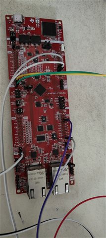
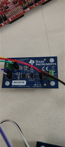
I am working to establish LIN communication between the Commander and Responder using the TLIN2029EVM and the LaunchXL F28P65X development board.
Currently, I am utilizing the C2000-Ware example for external loopback (LIN_ex7). The power is supplied externally with VBAT at 12V and a current of approximately 10mA and 5V input VCC on the EVM.
On the hardware setup, I have connected the TVS diode (D3) on the Commander side. I have also unplugged jumper JMP4 on the Responder side, and the respective configurations for both devices have been implemented.
I would appreciate any suggestions or recommendations to help ensure successful LIN communication.
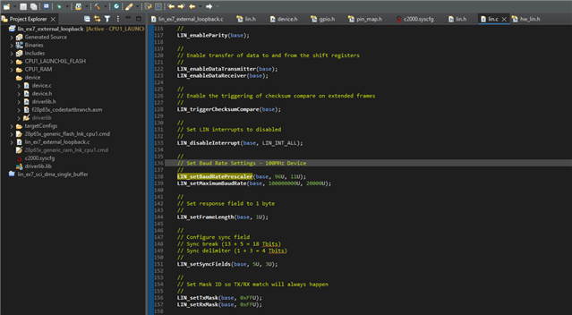
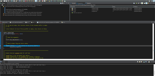
Below, I have included the example code I am working with:
//
// Included Files
//
#include "driverlib.h"
#include "device.h"
//
// Defines
//
#define FRAME_LENGTH 0x8
#define LIN_PASS 0xABCD
#define LIN_FAIL 0xFFFF
//
// Globals
//
volatile uint32_t level0Count = 0;
volatile uint32_t level1Count = 0;
volatile uint32_t vectorOffset = 0;
uint16_t result;
uint16_t error;
uint16_t txID = 0x1A, rxID = 0x1A;
uint16_t txData[8] = {0x11, 0x34, 0x56, 0x78, 0x9A, 0xAB, 0xCD, 0xEF};
uint16_t rxData[8] = {0xFF, 0xFF, 0xFF, 0xFF, 0xFF, 0xFF, 0xFF, 0xFF};
//
// Main
//
void main(void)
{
uint32_t dataIndex;
uint16_t error;
//
// Initialize device clock and peripherals
//
Device_init();
//
// Initialize GPIO and configure GPIO pins for LINTX/LINRX
//
Device_initGPIO();
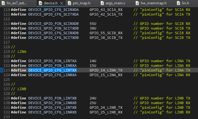
GPIO_setPinConfig(DEVICE_GPIO_CFG_LINTXA);
GPIO_setPinConfig(DEVICE_GPIO_CFG_LINRXA);
GPIO_setPinConfig(DEVICE_GPIO_CFG_LINTXB);
GPIO_setPinConfig(DEVICE_GPIO_CFG_LINRXB);
GPIO_setDirectionMode(DEVICE_GPIO_PIN_LINRXA, GPIO_DIR_MODE_IN);
GPIO_setPadConfig(DEVICE_GPIO_PIN_LINRXA, GPIO_PIN_TYPE_PULLUP);
GPIO_setQualificationMode(DEVICE_GPIO_PIN_LINRXA, GPIO_QUAL_ASYNC);
GPIO_setDirectionMode(DEVICE_GPIO_PIN_LINRXB, GPIO_DIR_MODE_IN);
GPIO_setPadConfig(DEVICE_GPIO_PIN_LINRXB, GPIO_PIN_TYPE_PULLUP);
GPIO_setQualificationMode(DEVICE_GPIO_PIN_LINRXB, GPIO_QUAL_ASYNC);
GPIO_setDirectionMode(DEVICE_GPIO_PIN_LINTXA, GPIO_DIR_MODE_OUT);
GPIO_setPadConfig(DEVICE_GPIO_PIN_LINTXA, GPIO_PIN_TYPE_STD);
GPIO_setQualificationMode(DEVICE_GPIO_PIN_LINTXA, GPIO_QUAL_ASYNC);
GPIO_setDirectionMode(DEVICE_GPIO_PIN_LINTXB, GPIO_DIR_MODE_OUT);
GPIO_setPadConfig(DEVICE_GPIO_PIN_LINTXB, GPIO_PIN_TYPE_STD);
GPIO_setQualificationMode(DEVICE_GPIO_PIN_LINTXB, GPIO_QUAL_ASYNC);
//
// Initialize the LIN module
//
LIN_initModule(LINA_BASE);
LIN_initModule(LINB_BASE);
//
// Set LIN B to responder Mode, LIN A to Commander Mode
//
LIN_setLINMode(LINB_BASE, LIN_MODE_LIN_RESPONDER);
LIN_setLINMode(LINA_BASE, LIN_MODE_LIN_COMMANDER);
LIN_enableParity(LINA_BASE);
LIN_enableParity(LINB_BASE);
//
// Set the ID to match while receiving
//
LIN_setIDResponderTask(LINB_BASE, rxID);
LIN_setIDByte(LINB_BASE, rxID);
//
// Set the frame length (number of bytes to be transmitted)
//
LIN_setFrameLength(LINA_BASE, 8);
LIN_setFrameLength(LINB_BASE, 8);
//
// Write data to Tx Buffer of LINA
//
LIN_sendData(LINA_BASE, txData);
//
// Set the message ID to initiate a header transmission.
// This causes the ID to be written to the bus followed by the
// data in the transmit buffers.
//
txID = LIN_generateParityID(txID);
LIN_setIDByte(LINA_BASE, txID);
//
// Wait until Transmit buffer is empty and has completed transmission
//
while(!LIN_isTxBufferEmpty(LINA_BASE));
//
//Wait for the Reception
//
while(!LIN_isRxMatch(LINB_BASE));
LIN_clearInterruptStatus(LINA_BASE,LIN_INT_ALL);
LIN_clearInterruptStatus(LINB_BASE,LIN_INT_ALL);
//
// Read the received data in the receive buffers
//
LIN_getData(LINB_BASE, rxData);
//
// Verify the transmitted data matches the received data
//
for (dataIndex=0; dataIndex < 8; dataIndex++)
{
if (rxData[dataIndex] != txData[dataIndex])
{
error++;
}
}
//
// Check if any data errors occurred
//
if(error == 0)
{
result = LIN_PASS;
}
else
{
result = LIN_FAIL;
}
//
// Example completed. Check "result" variable for completion status.
//
asm(" ESTOP0");
}
//
// End of File
//