TUSB320LAI: When using I2C DFP, where is VBUS_DET connected?

Part Number: TUSB320LAI
Other Parts Discussed in Thread: TUSB320

Tool/software:

Dear Specialists,

My customer is considering TUSB320LAI and has questions.

I would be grateful if you could advise.

---

(1) When using DFP mode only, it is stated on page 12 of the datasheet that VBUS_DET should be left floating.

On the other hand, on page 3 of the datasheet, it is stated that VBUS detection determines UFP attachment."

Furthermore, on page 12, it is stated that "VBUS detection is used to determine the attachment and detachment of a UFP and to determine the entering and exiting of accessary modes. VBUS detection is also used to successfully resolve the role in DRP mode."

If VBUS_DET is opened only in DFP mode, it will not be possible to determine the connection and disconnection of the UFP, and the start and end of accessory mode, as described above.

Is it possible to use VBUS_DET open in DFP only?

(2) In our case, we will use the battery as the DFP.

So when the other device is a UFP, we will output 5V from the battery.

In this case, ATTACHED_STATE on page 18 is read, will it become 7:6=10 Attached.SNK (UFP)?

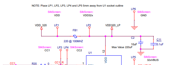
(3) In Figure 16 of the datasheet, VBUS_DET is connected in DFP in I2C Mode.

Figure 14 and Figure 15 also use I2C, VBUS_DET is floating.

When using this product (battery), we control the TUSB320 from I2C.

If using it DFP with I2C, does VBUS_DET need to be connected?

---

I appreciate your great help in advance.

Best regards,

Shinichi

  • Hi Shinichi,

    (1) When using DFP mode only, it is stated on page 12 of the datasheet that VBUS_DET should be left floating.

    On the other hand, on page 3 of the datasheet, it is stated that VBUS detection determines UFP attachment."

    Furthermore, on page 12, it is stated that "VBUS detection is used to determine the attachment and detachment of a UFP and to determine the entering and exiting of accessary modes. VBUS detection is also used to successfully resolve the role in DRP mode."

    If VBUS_DET is opened only in DFP mode, it will not be possible to determine the connection and disconnection of the UFP, and the start and end of accessory mode, as described above.

    Is it possible to use VBUS_DET open in DFP only?

    Yes, that is correct. VBUS_DET is only used to determine when a Source/DFP is sending VBUS when the TUSB320 is configured as a UFP, however this functionality is not needed when set as a DFP, as when set as a DFP, the ID pin of the TUSB320 is in charge of communicating to a connected voltage switch or MCU that VBUS should be sent through the type-C connector. The VBUS_DET pin will have no purpose in this configuration.

    (2) In our case, we will use the battery as the DFP.

    So when the other device is a UFP, we will output 5V from the battery.

    In this case, ATTACHED_STATE on page 18 is read, will it become 7:6=10 Attached.SNK (UFP)?

    Yes, this is correct. Please ensure VBUS is not being sent until have the ID pin is pulled low, or that may affect the CC negotiation process.

    (3) In Figure 16 of the datasheet, VBUS_DET is connected in DFP in I2C Mode.

    Figure 14 and Figure 15 also use I2C, VBUS_DET is floating.

    When using this product (battery), we control the TUSB320 from I2C.

    If using it DFP with I2C, does VBUS_DET need to be connected?

    This is likely a precaution in case the mode of the TUSB320 is changed via I2C, as I2C can be used to set the TUSB320 as a DFP, UFP, or DRP. If you are not intending to switch the mode from DFP to UFP or DRP, you can still leave this pin floating.

    Please let me know if you have any other questions!

    Thanks,

    Ryan

  • Hi Ryan,

    Thank you for your reply.

    I'll share your answer with the customer.

    When the customer has an additional question, I consult you again.

    I appreciate your great help and cooperation.

    Best regards,

    Shinichi

  • Hi Shinichi,

    Sounds good, I will leave this thread open in the mean time.

    Thanks,

    Ryan

  • Hi Ryan,

    The customer has additional questions.

    Could you please advise?

    ---

    Just to be sure, is the following understanding correct?

    This may be a repetitive question, but I would appreciate your answer.

    Question 1

    If the other party is a UFP,
    when ATTACHED_STATE on P18 is read, 7:6 = 10 Attached.SNK (UFP)

    If the other party is a DFP,
    when ATTACHED_STATE on P18 is read, 7:6 = 01 Attached.SRC (DFP)

    Question 2

    Please ensure VBUS is not being sent until have the ID pin is pulled low, or that may affect the CC negotiation process.

    it may affect the CC negotiation process.

    It is written that the ID pin is asserted low when the CC pin detects a device connection.

    Is it correct to understand that the ID pin goes low in all cases: "Attached.SNK", "Attached.SRC", and "Attached to an accessory"?

    Question 3

    In our application, the PORT pin (pin 3) is fixed to H (DFP).
    Is the sequence as follows?
    ID pin is low level ⇒ Check ATTACHED_STATE state ⇒ 7:6=10 Attached.SNK ⇒ 5V (VBUS) output

    Question 4

    Also, when ATTACHED_STATE is 7:6=11 Attached to an accessory, is it okay to output 5V (VBUS)?

    ---

    I appreciate your great help in advance.

    Best regards,

    Shinichi

  • Hi Shinichi

    Question 1

    If the other party is a UFP,
    when ATTACHED_STATE on P18 is read, 7:6 = 10 Attached.SNK (UFP)

    If the other party is a DFP,
    when ATTACHED_STATE on P18 is read, 7:6 = 01 Attached.SRC (DFP)

    Correct.

    Question 2

    Please ensure VBUS is not being sent until have the ID pin is pulled low, or that may affect the CC negotiation process.

    it may affect the CC negotiation process.

    It is written that the ID pin is asserted low when the CC pin detects a device connection.

    Is it correct to understand that the ID pin goes low in all cases: "Attached.SNK", "Attached.SRC", and "Attached to an accessory"?

    The ID pin status is not necessarily attached to the reg 0x09, it is just meant to be a secondary way of communicating when something is attached. In this case, the ID pin should go low to match the Attached.SNK state, however it does not go low with the Attached.SRC state. The ID pin only goes low when the TUSB320 is configured as a DFP.

    For the accessory scenario, an accessory can be either a DFP or a UFP. As such, when the status of the bit is "attached to an accessory", the TUSB320 can potentially be configured as a DFP or a UFP, if it is set as a DRP.

    Question 3

    In our application, the PORT pin (pin 3) is fixed to H (DFP).
    Is the sequence as follows?
    ID pin is low level ⇒ Check ATTACHED_STATE state ⇒ 7:6=10 Attached.SNK ⇒ 5V (VBUS) output

    If possible, I would recommend just following the ID pin for enabling VBUS. While you can also monitor the attached_state bit, typically just monitoring the ID pin is simplest.

    Question 4

    Also, when ATTACHED_STATE is 7:6=11 Attached to an accessory, is it okay to output 5V (VBUS)?

    Again, an accessory can be both a DFP and a UFP, so if set as a DRP, it can be hard to be determine what the orientation is. However, if set as a DFP, then it should only connect to UFP devices, so it should be okay in this scenario.

    Thanks,

    Ryan

  • Hi Ryan,

    Thank you for your reply.

    I shared your answer with the customer, they have additional questions.

    Could you please advise?

    ーーー

    ・Question 1

    If possible, I would recommend just following the ID pin for enabling VBUS. While you can also monitor the attached_state bit, typically just monitoring the ID pin is simplest.

    You mentioned that by monitoring only the ID pin, if it goes low, VBUS is enabled (supplied to the device),

    Conversely, if ID goes high while VBUS is enabled (supplied to the device), VBUS is disabled (supply to the device is stopped), is this understanding correct?

    *There is no need to check attached_state to enable/disable VBUS

    ・Question 2

    Our specifications are fixed to DFP.

    In this case, we believe the following register settings are sufficient.

    Could you please let us know if there are any other registers that should be set?

    ・CURRENT_MODE_ADVERTISE: Sets the supply current.
    ・DISABLE_UFP_ACCESSORY: Enables/disables the UFP accessory.

    ---

    I appreciate your great help and cooperation.

    Best regards,

    Shinichi

  • Hi Shinichi,

    If possible, I would recommend just following the ID pin for enabling VBUS. While you can also monitor the attached_state bit, typically just monitoring the ID pin is simplest.

    You mentioned that by monitoring only the ID pin, if it goes low, VBUS is enabled (supplied to the device),

    Conversely, if ID goes high while VBUS is enabled (supplied to the device), VBUS is disabled (supply to the device is stopped), is this understanding correct?

    The ID pin going high would indicate that the CC lines have been disconnected, so VBUS would also be disabled because the ID pin will disable the power switch or GPIO it is attached to, yes.

    By ID going low and enabling VBUS, I just mean that whatever switch or GPIO it is attached to should begin to send VBUS when it sees the ID pin go low.

    Could you please let us know if there are any other registers that should be set?

    ・CURRENT_MODE_ADVERTISE: Sets the supply current.
    ・DISABLE_UFP_ACCESSORY: Enables/disables the UFP accessory.

    These are the only registers you may need to change depending on your systems needs, yes. There shouldn't be any registers essential for DFP functionality.

    Please let me know if you have any other questions.

    Thanks,

    Ryan

  • Hi Ryan,

    Thank you for your reply.

    I'll share your answer with the customer.

    When the customer has an additional question, I consult you again.

    I appreciate your great help and cooperation.

    Best regards,

    Shinichi

  • Hi Shinichi,

    No worries. If anything else comes up, feel free to respond back.

    Thanks,

    Ryan

  • Hi Ryan,

    Thank you for your reply.

    With your support, he customer's consideration is going smoothly.

    And the customer has additional questions.

    Could you please advise?

    ---

    (1) In our circuit configuration, the ID pin is connected to a microcontroller, and we're thinking of outputting VBUS (turning the MOSFET on/off) from another output port on the microcontroller depending on the ID pin's L/H condition.

    The reason is that our batteries have three output patterns: fan output, TYPE-A output, and TYPE-C output. We want the microcontroller to determine which output to use depending on the conditions.

    If the ID pin were connected directly to the above MOSFET, it would become standalone and inflexible, so we'd like the ID pin to be received by the microcontroller first, and then control the VBUS output.

    Is this usage possible?

    Or would it be better to connect the ID pin directly to a MOS that controls VBUS on/off?

    (2) Also, this is a basic question, but what kind of accessory is "attached to an accessory"?

    Please let us know, even if you're just showing us a specific product and image.

    *I've previously heard that there are UFPs and DFPs.

    ーーー

    I appreciate your great help and cooperation.

    Best regards,

    Shinichi

  • Hi Shinichi,

    (1) In our circuit configuration, the ID pin is connected to a microcontroller, and we're thinking of outputting VBUS (turning the MOSFET on/off) from another output port on the microcontroller depending on the ID pin's L/H condition.

    The reason is that our batteries have three output patterns: fan output, TYPE-A output, and TYPE-C output. We want the microcontroller to determine which output to use depending on the conditions.

    If the ID pin were connected directly to the above MOSFET, it would become standalone and inflexible, so we'd like the ID pin to be received by the microcontroller first, and then control the VBUS output.

    Is this usage possible?

    Or would it be better to connect the ID pin directly to a MOS that controls VBUS on/off?

    That should be perfectly fine. Using an MCU to monitor the ID pin and then output a signal depending on the status of the pin is a good way of controlling VBUS.

    (2) Also, this is a basic question, but what kind of accessory is "attached to an accessory"?

    Please let us know, even if you're just showing us a specific product and image.

    *I've previously heard that there are UFPs and DFPs.

    Correct, there are both DFP and UFP audio/debug accessory. An audio accessory uses the type-C pins to transfer audio signals, so for example a AUX jack dongle for type-C, while a debug accessory uses the type-C pins to transmit debug signals, like UART or I2C signaling. These are the two different types of accessories that can be present in a type-C ecosystem.

    Please let me know if there are any other questions.

    Thanks,

    Ryan

  • Hi Ryan,

    Thank you for your reply.

    I shared your answer with the customer.

    The customer has an additional question, could you please advise.

    ---

    I plan to supply 3.3V to the VDD pin.

    The VBUS_DET pin on the DFP will be floating.

    3.3V will be supplied to CC1 and CC2.

    Are there any problems with CC1/CC2 detection?

    It is 5V is normally used. 

    How are CC1/CC2 detected even though the voltages are different?

    ---

    I appreciate your great help and cooperation.

    Best regards,

    Shinichi

  • Hi Shinichi,

    I plan to supply 3.3V to the VDD pin.

    Does the customer plan on advertising 3A at all? If so, then VDD will need to be greater than 3.5V, preferably 5V. If not, then the CC controller will not be able to advertise 3A.

    3.3V will be supplied to CC1 and CC2.

    Are there any problems with CC1/CC2 detection?

    Is the customer supplying 3.3V directly to CC1/2? This is not necessary, the CC controller will control the voltage of these pins, they just need to be routed to the connector. This is important, as the voltage provided by the CC controller changes depending on the advertised current. It can not just be pulled-up to 3.3V.

    How are CC1/CC2 detected even though the voltages are different?

    CC pin detection is based on seeing Rd from a connected device.

    Please have the customer review my previous notes.

    Thanks,

    Ryan

  • Hi Ryan,

    Thank you for your reply.

    The customer confirmed operation using the TUSB320LAIEVM and has questions.

    Could you please advise?

    ---

    We confirmed operation using the TUSB320LAIEVM.

    Operation was confirmed after changing the VDD from 5.5V to 3.3V.

    Dip Switch setting

    SW1.1 ON

    SW1.2 OFF

    SW1.3 OFF

    SW1.4 OFF

    SW1.5 OFF

    SW1.6 ON

    SW1.7 ON

    SW1.8 OFF

    I2C communication was not used.

    In this condition, two mobile battery (5V3A) and smart phone for PD were connected and operation was confirmed.

    Although it varied depending on the battery type, 2.4A/1.9A was supplied. (We believe the current output was not possible due to the drop in battery voltage.)

    The CC1, CC2, voltages and current  for each device are as follows:

    CC1 CC2 Voltage Current
    Mobile Battery1 0.175V 0.603V 4.546V 2.483A
    Mobile Battery 2 0.233V 0.531V 4.667V 1.948A
    Smart Phone 0.319V 0.494V 4.794V 1.459A

    This appears to indicate that even when using a 3.3V VDD, advertising occurred and a 5V3A was set, is this understanding correct?

    However, as you mentioned(datasheet description), a VDD of 3.5V or higher is required.

    Is operation of the device not guaranteed with a VDD of 3.3V?

    If the answer is no, it is not possible to advertise an output of 3A, but settings (advertisements) of Default (500 mA / 900 mA) or Mid (1.5 A) are possible?

    ---

    I appreciate your great help and cooperation.

    Best regards,

    Shinichi

  • Hi Shinichi,

    I would not attempt to advertise 3A with an insufficient amount of power. This may affect functionality. It is better to stay at default or 1.5A to ensure proper functionality.

    I would recommend checking these settings to confirm that the TUSB320 is configuring as a DFP or a UFP. I know you currently have it set through the DIP switch to be a DFP, but I would still like to confirm.

    The default advertisement should be 900mA max, unless set differently through I2C.

    I would also test using a 5V VCC, as we have the EVM designed for a 5V DC in or 5V VBUS. Has the customer already tested with 5V?

    Thanks,

    Ryan

  • Hi Ryan,

    The customer is using I2C mode, not GPIO mode.

    I deleted last post because of my misunderstanding. I'm so sorry.

    Could you please ignore?

    I could obtain the customer's feedback, could you please advise?

    --- 

    We are using I2C mode, but I2C is not established.

    D1, D2 and D3 is OFF. D4 is ON.

    To clarify the conditions,
    I confirmed that the TUSB320LAIEVM was operating at VDD3.3V in I2C mode.
    I2C was not using.
    At this time, the TUSB320LAI should be set to its default setting(500mA/900mA).
    When I checked its operation, the voltage and current values were not default.

    Could you please why is this happening?

    CC1 CC2 Voltage Current
    Mobile Battery1 0.175V 0.603V 4.546V 2.483A
    Mobile Battery 2 0.233V 0.531V 4.667V 1.948A
    Smart Phone 0.319V 0.494V 4.794V 1.459A

    When VDD=5V, Mobile Battery2 and Smart Phone were charging 5V and 0.5A.

    I appreciate your great help and cooperation.

    Best regards,

    Shinichi

  • Hi Shinichi,

    We are using I2C mode, but I2C is not established.

    So does the customer have SW1.4 ON then? If they do not want to use I2C mode, they should leave this switch off.

    If they have the ability to, can they read register 0x08 and see what that returns if they are going to have I2C mode enabled?

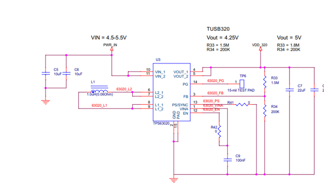
    Again, we expect this EVM to be used with a power supply of 5V, as reflected by the power system of the EVM:

    If the customer is not using the expected VDD, functionality may not be as expected.

    CC1 CC2 Voltage Current
    Mobile Battery1 0.175V 0.603V 4.546V 2.483A
    Mobile Battery 2 0.233V 0.531V 4.667V 1.948A
    Smart Phone 0.319V 0.494V 4.794V 1.459A

    Would it be possible for the customer to take these values with a 5V VDD as well? What about powering through VBUS?

    D4 indicates the ID pin is low though, so the device is set as a DFP.

    Thanks,

    Ryan

  • Hi Ryan,

    I talked with the customer.

    The customer changed VDD5V and VBUS 5V.

    However, they could not establish I2C communication, due to the NACK is returned.

    Could you please advise how to solve?

    TUSB320 I2C Setting and NACK 20250819.xlsx 

    The EVM has been modified to connect to our battery board. An MCU is mounted on the battery board.

    VBUS (5V) is connected to TP5 via our USB output (5V).
    *Pattern cut between "PWR_IN" and "VIN-1 and VIN-2 of U3."
    *Jumper J8 is removed.
    *LP2 and VDD_320 are supplied with 5V from an external power supply.
    *TUSB320's EN is low, and ADDR is 5V (high input).
    *R11/R13 (I2C) are removed. J1-1 and J-3 are connected to the I2C terminals on the battery board, and 3.3V is internally pulled up with a 4.7kΩ resistor.

    I appreciate your great help and cooperation.

    Best regards,

    Shinichi

  • Hi Shinichi,

    Just to confirm, your customer is trying to read/write to address 0x67 correct? R10 is installed next to SW1?

    Is there any signal on the CC lines? I also want to make sure the CC controller is actually enabling, it sounds like there have been a large number of adjustments made to this EVM.

    VDD is ramping within 25ms as well, correct?

    Thanks,

    Ryan

  • Hi Ryan,

    Thank you for your reply.

    I could obtain the customer's feedback.

    Could you please see listed below.

    ---

    Just to confirm, your customer is trying to read/write to address 0x67 correct? R10 is installed next to SW1?

    Yes, in accordance with datasheet page 15, ADDR=H, so 11001110 (CE) is being sent. *The result is the same (no ACK) even if ADDR=L and 10001110 (8E) is sent.

    Result is NACK.

    I also tried setting ADDR=L and sending 10001110 (8E), but the result was the same (NACK).

    R10 is installed (implemented) next to SW1.

    Is there any signal on the CC lines? I also want to make sure the CC controller is actually enabling, it sounds like there have been a large number of adjustments made to this EVM.

    CC1=4.7V, CC2=4.7V. *The TYPE-C connector is open (nothing connected).

    When I connect a smartphone to the TYPE-C connector, D4=red lights up, so I think it's enabled.

    I'm not sure any other detail.

    VDD is ramping within 25ms as well, correct?

    VDD rose within 25 ms.

    ---

    I appreciate your great help and cooperation.

    Best regards,

    Shinichi

  • Hi Shinichi,

    Sounds like the CC controller is enabling as a DFP, properly connecting, and functioning in general, so it sounds like there are no issues there.

    Can the customer try 0x67 for the I2C address, per what is listed in the pin description for the ADDR pin?

    Thanks,

    Ryan

  • Hello,

    Closing thread due to inactivity. If you have any follow-up questions or concerns, feel free to reply.

    Thanks,

    Ryan