This thread has been locked.

If you have a related question, please click the "Ask a related question" button in the top right corner. The newly created question will be automatically linked to this question.

TCAN1044A-Q1: Could not measure the Internal Resistance of CAN IC

Part Number: TCAN1044A-Q1

Tool/software:

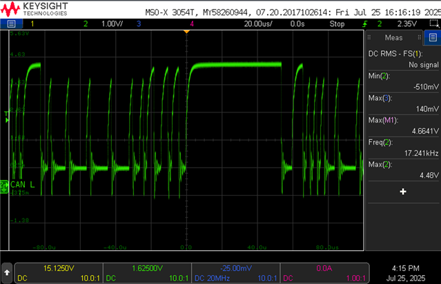
We attempted to measure the internal resistance of the TCAN1044AVDRBRQ1 IC. While we obtained accurate results for CAN High, we encountered issues with CAN Low. The following procedure was used for testing:
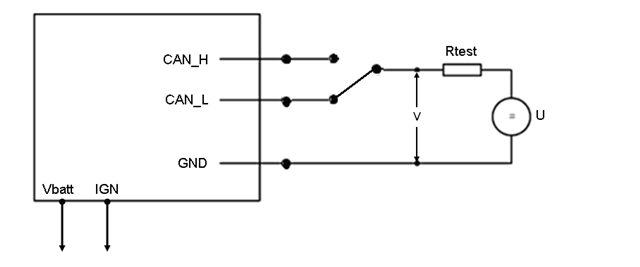
Procedure:

  • Measure the precise value of Rtest using an ohmmeter.
  • Connect an oscilloscope to observe the voltage ('V') between CAN_H and GND for Rin_CAN_H, and between CAN_L and GND for Rin_CAN_L.
  • Power up the ECU at a supply voltage Vbatt of 13.8 V.
  • Set U (another power supply) to 5 V.
  • Measure 'V' at a recessive level.
  • Calculate Rin using the formulas:
    • Rin_CAN_L = Rtest * (VCAN_L - V) / (V - U)
    • Rin_CAN_H = Rtest * (VCAN_H - V) / (V - U)

VCAN_H and VCAN_L are the output voltages of the CAN_H and CAN_L lines, respectively, during the recessive state when the supply voltage is 13.8 V.

We are observing CAN communication on the line.

Please advise on why this is happening.


  • Hi Jayenthiran,

    The test method is not ideal for CAN_L because CAN_L is actively driven low in recessive, and external voltages interfere with transceiver’s operation. Measuring input resistance this way effectively fights the drivers output stage, causing bus state changes and triggering communication.


    I.e, connecting Rtest between CAN_L and the 5 V can unintentionally drive CAN_L high, creating a differential voltage interpreted by the transceiver as a dominant state. Hence, triggering bus communication or error frames.

    Unlike CAN_H (which is normally biased high during recessive), CAN_L is biased low (~ground), so connecting it up to 5 V for this measurement interferes more severely with bus idle state.

    Your voltage divider method is valid only if VCAN is an open-circuit voltage at recessive level and no active driver fights your measurement current. For CAN_L, the transceiver actively drives the recessive state low, so external voltages can disturb its output stage.

    I would recommend to ensure the device is in standby mode similar to the data sheet’s conditions for RIN, to avoid driver influence. Utilize the datasheet’s for input leakage current specifications instead of voltage divider method. If necessary, measure current directly using a source measuring unit and avoid applying 5 V directly to CAN_L as the CAN_L recessive voltage is close to ground + ~0.5-1.5 V, not 5 V. Applying 5 V can exceed input voltage levels and cause the observed abnormal behavior. Further ensure the CAN bus is not active. If the CAN bus is active, other nodes may interpret your test as data or error, causing unintended communication, thanks. 

    Best Regards,

    Michael. 

  • Hi Michael,


    We experimented with a different IVI that utilizes the same Micro and CAN IC, and observed a consistent DC voltage of 4.35V for CAN L. How can this occur? Could there be something we're overlooking? Apart from the Micro software, everything else is identical.

    Warm Regards

    Jay

  • Hi Jay,

    This can indicate the pin is floating or pulled up, no termination or the device is damaged, incorrect mode (micro configuring the device into standby mode incorrectly, for example) or VCC / GND may be misconnected.

    Since the Micro is the only change, it can be worth double checking the firmware or GPIO settings. I.e., The device seems to be forced into a state where it cannot properly drive CAN_L low most likely due to 5 V applied through a resistor to an actively driven pin, incorrect firmware setting on TXD or STB and any additional hardware configurations from internal pull-ups on the micro, incorrect supply, missing ground etc., thanks.

    Best Regards,

    Michael.