This thread has been locked.

If you have a related question, please click the "Ask a related question" button in the top right corner. The newly created question will be automatically linked to this question.

THVD8000: The application of THVD8000

Part Number: THVD8000

Tool/software:

Hello Expert,

May I check an application scenario with you?

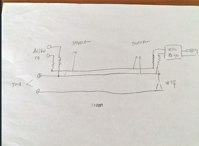
 This is the scenario I planned for carrier transmission 100 m with low voltage carrier Two wires are 36 V AC sine wave for motor drive board power supply, one of which shares a single cable cross-sectional area of the welded loop 50 mm2 The average current of the welded loop is 500 A maximum. the current will fluctuate, typically within 100 volts, Please help me analyze if our chip can achieve, and if we can achieve carrier frequency, you can probably get how much 

Best regards,

Wenting

  • Hi Wenting,

    I am just trying to better understand the system that you are looking at.

    Is the concern interference ? As I am reading it - there is no electrical connection between the 500A line and 36VAC 5A line - but one of the wires is very close - is that correct? 

    The main concern here is going to be that is a ton of current and if varies with time it can cause a lot of interference - and some of this interference will be differential because one cable is going to be much closer so one cable is going to experience more interference - which isn't great for a differential device. 

    Please let me know if my understanding is correct to see if we have something that may work - I will say we haven't tested anything like this - but we may be able to find a workaround I just need to fully understand the system and the concern first. 

    Best,

    Parker Dodson

  • Hello Parker,

    Thanks for your quick reply.

    there are two wires of 36VAC, one cable of 50mm2, the overall cable outer diameter is 15mm, where the outer insulation thickness is about 1.5mm, Another thin insulated wire with a cross-sectional area of 2 mm2 is placed inside an airpipe with a wire insulation thickness of about 1.5 mm. The cables and hoses are tied together with tie straps. 

    Best regards,

    WENTING 

  • Hi Wenting,

    So I am skeptical this would work - the interference from the cable sharing the cross section with the high current (with large potential swings) would cause a lot of interference and could come across as 1) differential noise (bad data) or 2) destructive interference that leads to part damage due to the potential swings. 

    In general 36VAC at 5A is okay for standard LV AC applications (the current is high though - so suitable inductors may be a challenge) - explanation on how to do that here:  https://www.ti.com/lit/an/slla600/slla600.pdf?ts=1753733388112

    However - there could be a work-around - but the solution is much more complicated - we consider it our high voltage implemenation - but it is not differential - it only sends data on one wire - and could maybe work to send data on one wire - however even though the worst of the interference would be mitigated there could still be interference which could still compromise data integrity - the high voltage implemenation is shown here: https://www.ti.com/lit/an/slla590/slla590.pdf?ts=1693491025500&ref_url=https%253A%252F%252Fwww.ti.com%252Fproduct%252FTHVD8000

    Option 2 doesn't use inductors - it uses an additional line driver + transformers to inject data onto one line of a power bus - it was originally designed for AC Mains applications - but is also used for solar power inverters. 

    One thing I would suggest if they want to try looking at this - because it may not be impossible to do - is to get the high voltage reference board and test it in system to see if it works for what it is needed - I am skeptical it will work, but it might. Reference board for high voltage implemenation: https://www.ti.com/tool/PLC010935BP

    The reason I'd suggest the high voltage is for 2 main reasons:

    1. The potential swings from the high current wire could induce dangerous transients on the bus - the HV implemenation is meant for 120VAC systems to 1kV+ applications - so this system is much more robust than a standard AC implemenation (which has a risk of breaking during usage)

    2. It only communicates data on 1 wire instead of 2 - you could inject data into the wire that doesn't share a cross section with high current - so total interference would be reduced.

    Please look through the attached material and if you have any other questions please let me know!

    Best,

    Parker Dodson

  • Hello Parker,

    Really thanks for you explanation in details. 

    We are interested in option 2 with using transformers. Do you have more materials on how to design the transformer?

    Besides, we are worry about the voltage drops in 100m-longth wire. Do you have some advices?

    Best regards,

    Wenting

  • Hi Wenting,

    For the transformer there are three main considerations if they are going to use a custom transformer. 

    1. We have only tested at about a 1:1.3 transformer (but usually we just suggest a 1:1 - so voltage and current stay the same on both sides of isolation barrier)

    2. The core should be optimized for the targeted carrier frequency +/-25% to account for modulator tolerance. 

    3. The insertion loss must be low - so the leakage inductance on the transformer also needs to be very low relative to carrier frequency. This will depend on "load seen" by the driver - but for this specific system the load should be relatively larger since we are focused on the 36VAC line. Leakage inductance will directly translate to insertion loss of the signal. 

    Another consideration - which isn't as important as long as the HV interface capacitor is properly sized - is that the transformer should be able to work at the systems voltages - the HV interface capacitor should attenuate most of the 36VAC across it before it reaches the coils - but it is something to consider as well. 

    For the distance - you will maximize the distance at 125KHz modulation frequency - in general the THVD8000 can transmit up to 1.5km in ideal conditions at 125KHz - the high voltage implementation will decrease that a bit since it isn't a true differential bus - but it can be slightly offset by increasing the gain on the additional line driver - right now the line driver in our documentation is set to unity gain - but increasing the gain could result in a slightly longer transmit distance. However at 100m I really don't think that would be a huge issue. The real question is going to be what is the data rate - the modulation frequency should be >= 10x data rate - so a data rate from 0bps to 12.5kbps can be covered by the 125KHz modulation frequency - if you have higher data rates you will have to increase the modulation frequencies. However - I don't think I have ever seen a case in the last 3-4 years of me covering this device where it couldn't transmit across 100m - that is usually pretty doable with our device and I don't think there should be too much concern. But as always this is something that actual testing will clarify the best - but with what I have seen and how I know this type of application usually works 100m should be fine. The biggest concern is if the cross talk from the 500A line could impact the data signal too much - but that is less about length of bus and more just the high current being ran next to it. 

    Please let me know if you have any other questions and I will see what I can do!

    Best,

    Parker Dodson