Part Number: TUSB1142
Tool/software:
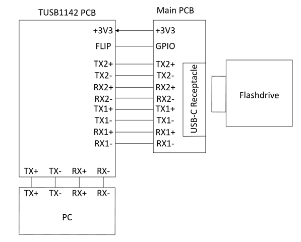
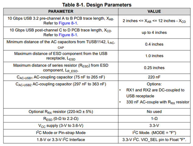
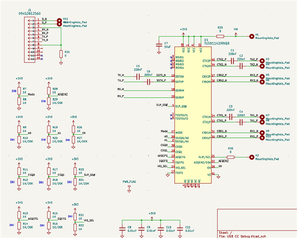
Hello, I have the following schematic made; all my 3.1 connections are coming from wires soldered from another board. These wires are really short and are USB 90-Ohm wires. The layout of the board was taken into consideration from the datasheet, there is at least 0.4 inches of space from the series caps from the chip, and they are direct. The connector J1 uses a custom cable I made that I know is reliable because I've tested with it before. Pin 21 (Flip) comes from a GPIO pin on the other board which also matches the logic with the TUSB1142 (GPIO = 1 = CC2 is selected, GPIO = 0 = CC1 is selected). +3V3 is also supplied from the board as well.
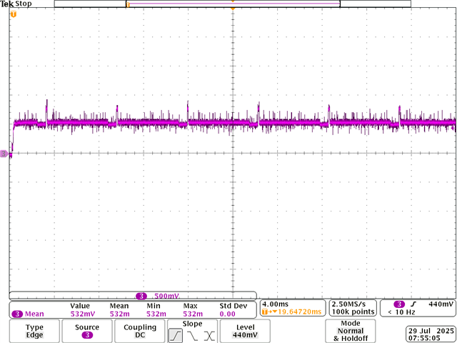
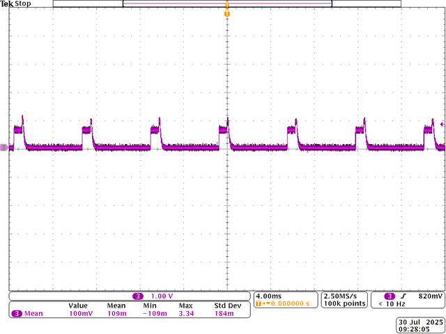
My current method of testing is plugging in J1 into my PC, and plugging in a flash drive into the USB-C receptacle that the wires come from. From my observations on the oscilloscope, it seems that data may be passing through the chip however my PC is still not able to see the flash drive. I've tried adjusting the gain from low to high, then somewhere in between, I've tried turning on/off AEQ, I've tried removing the series capacitors, I've pulled SLP-S0# high, low, and even floating and I'm still not able to find the issue as to why data is not passing through properly.
I don't believe it is a hardware issue, I've done sketchier things with longer wires that aren't meant for signals and was able to get it to work. I believe there's a configuration I'm not doing right, I've looked through the datasheet a good handful of times, re-read the pin descriptions but can't find what could be causing the issue.
My end goal is simply to pass USB3.1 data using this chip. I'd appreciate if I can get any clarification if I'm doing something wrong.
Please let me know if there's anything that I need to clear up.